A four-redundancy simulation signal hardware voting circuit

A voting circuit and analog signal technology, applied in logic circuits using specific components, logic circuits using semiconductor devices, etc., can solve the problems of low design cost and short design cycle, and achieve low production costs, simple and practical circuits, and simplification. design effect

Active Publication Date:
View PDF3 Cites 15 Cited by
  • Summary
  • Abstract
  • Description
  • Claims
  • Application Information

AI Technical Summary

Problems solved by technology

[0005] The technical problem to be solved by the present invention is: to propose a pure hardware circuit for four-redundancy analog signal voting with short design period, low design cost and high reliability, so as to solve the synthesis of four-redundancy signal output in the redundancy system question

Method used


Image

  • A four-redundancy simulation signal hardware voting circuit

Examples


Embodiment Construction

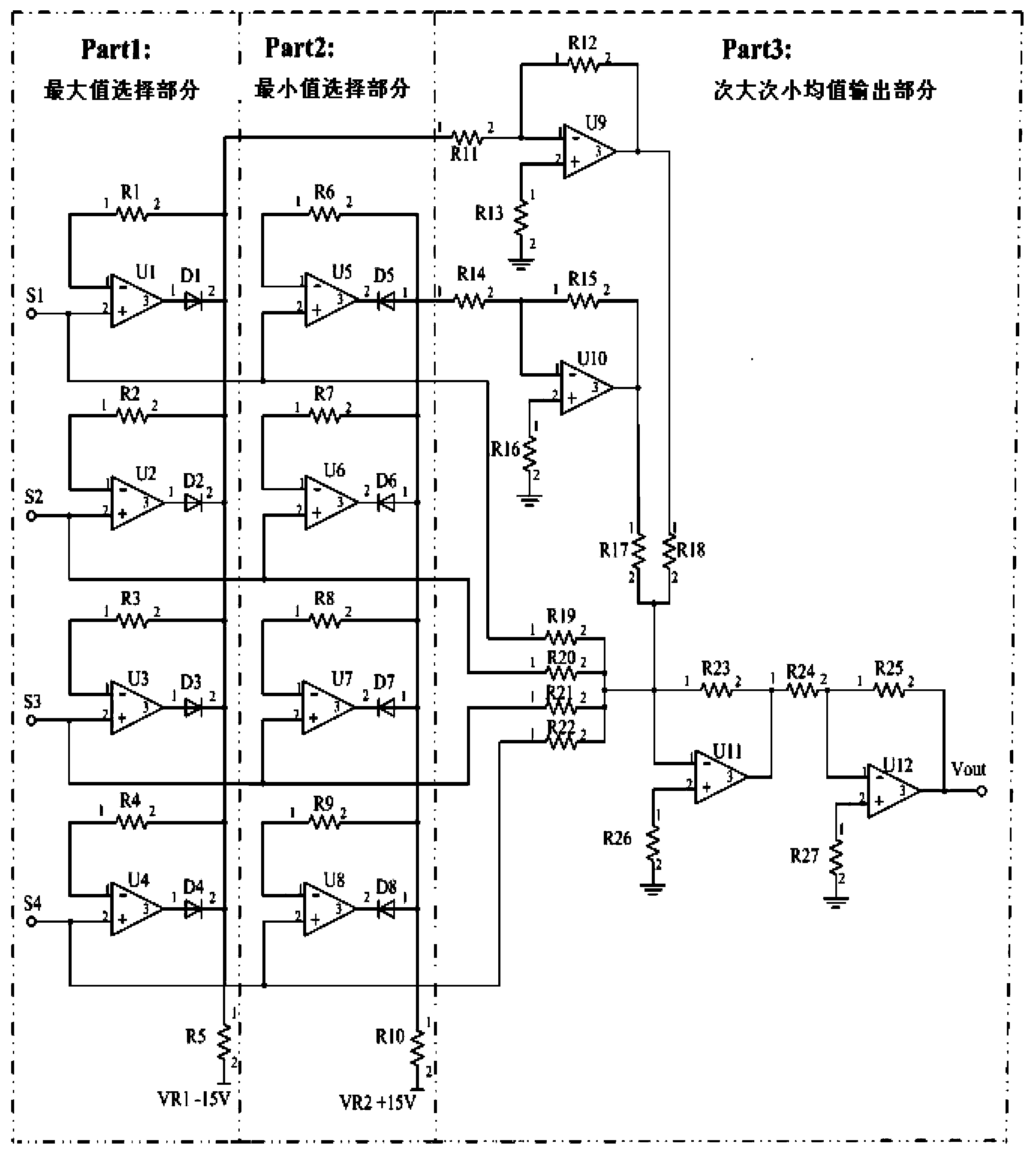
[0009] The specific embodiments of the present invention will be further described below in conjunction with the accompanying drawings.

[0010] see figure 1 , a four-redundancy analog signal hardware voting circuit of the present invention mainly includes four four operational amplifier chips with high gain, eight diodes and some resistors; the four-redundancy input signals are respectively S1, S2, S3, S4 ; Input signal S1 is connected to input 2 of operational amplifiers U1 and U5 and input 1 of resistor R19; input signal S2 is connected to input 2 of operational amplifiers U2 and U6 and input 1 of resistor R20; input signal S3 is connected to operational amplifier U3 , U7 input 2, resistor R21 input 1; input signal S4 is connected to operational amplifier U4, U8 input 2, resistor R22 input 1; operational amplifier U1, U2, U3, U4, U5, U6, U7 , U8, U9, U10, U11, and U12 are respectively connected to input 1 ends of resistors R1, R2, R3, R4, R6, R7, R8, R9, R12, R15, R23, and...


PUM


Abstract

The invention belongs to the technical field of telex flight control systems, and especially relates to a four-redundancy simulation signal hardware voting circuit. The four-redundancy simulation signal hardware voting circuit of the invention mainly comprises a quad operational amplifier chip with a high gain, eight diodes and several resistors. The circuit of the invention is simple and practical. The production cost is low. The circuit is reliable. Lagging of signal selection voting will not occur. The design and the debugging are convenient. A synthesis problem of four-redundancy driving signals of a control system can be easily solved, and intersecting redundancy voting from a controller to execution parts is realized. The design of the controller is enabled to be simplified so as to raise the reliability of the system.

Description

technical field [0001] The invention belongs to the technical field of fly-by-wire flight control systems, in particular to a four-redundancy analog signal hardware voting circuit. Background technique [0002] The fly-by-wire flight control system adopts redundancy technology to improve its own reliability, and the redundancy synthesis technology of the fly-by-wire system is also varied. At present, the redundancy signal synthesis technology commonly used in the fly-by-wire flight control system mainly consists of the following types: [0003] Method 1: Use the controller to collect analog redundancy signals, vote on the signals through software algorithms and output the voting value; Method 2: Use online monitoring technology to monitor redundant components (such as controllers) online, when faults are found, pass additional Hardware, generally the relay circuit cuts off the output of the faulty channel and converts it to the normal channel output; Method 3: Control the ou...

Claims


Application Information

Patent Timeline
Patent Type & Authority Applications(China)
IPC IPC(8): H03K19/08
Inventor 杜永良
Why Eureka
Try Eureka