Downlink UE-specific DM-RS transmission method, UE and network-side device

A technology of DM-RS and transmission method, which is applied in the fields of downlink user-specific DM-RS transmission method and UE and network side devices, which can solve the problems of DM-RS transmission method without reducing overhead, reduce transmission overhead, and improve throughput Effect

Active Publication Date: 2014-01-15
DATANG MOBILE COMM EQUIP CO LTD
View PDF4 Cites 21 Cited by
  • Summary
  • Abstract
  • Description
  • Claims
  • Application Information

AI Technical Summary

Problems solved by technology

However, there is currently no overhead-reducing DM-RS transmission method based on the characteristics of Indoor / hotspot scenarios

Method used


Image

  • Downlink UE-specific DM-RS transmission method, UE and network-side device
  • Downlink UE-specific DM-RS transmission method, UE and network-side device
  • Downlink UE-specific DM-RS transmission method, UE and network-side device

Examples


Embodiment approach

[0088] ① Determine that the PDSCH adopts the second type of DM-RS resource mapping method in the transmission subframe whose subframe number n satisfies (n-offset1) modS1=0, and uses the first type of DM-RS in other transmission subframes of the PDSCH Resource mapping method;

[0089] Or, it is determined that the PDSCH adopts the first type of DM-RS resource mapping method in the transmission subframe whose subframe number n satisfies (n-offset1) modS1=0, and that the PDSCH adopts the second type of DM-RS in other transmission subframes Resource mapping method;

[0090] Wherein, S1 is a period value agreed in advance or configured by high-level signaling, and offset1 is a subframe number offset value agreed in advance or configured by high-level signaling.

[0091] ② Determine that PDSCH adopts the first type of DM-RS resource mapping method in time division duplex TDD special subframes, and that PDSCH adopts the second type of DM-RS resource mapping method in other transmis...


PUM


Abstract

The invention discloses a downlink UE-specific DM-RS transmission method, UE and a network-side device. The method comprises: according to a pre-appointment of the UE and a network side, or according to configuration information sent by the network side, determining a DM-RS resource mapping manner used by a downlink channel, the DM-RS resource mapping manner comprising a first class DM-RS resource mapping manner and a second class DM-RS resource mapping manner, the first class DM-RS resource mapping manner being a DM-RS resource mapping manner defined in a long term evolution-advanced (LTE-A) Rel-10 system, and the second class DM-RS resource mapping manner being a mapping manner having reduced DM-RS occupied resources relative to the first class DM-RS resource mapping manner; and in a transmission resource of the downlink channel, acquiring DM-RS information according to the determined DM-RS resource mapping manner. According to the present invention, the DM-RS transmission overheads can be reduced, and the throughput can be improved.

Description

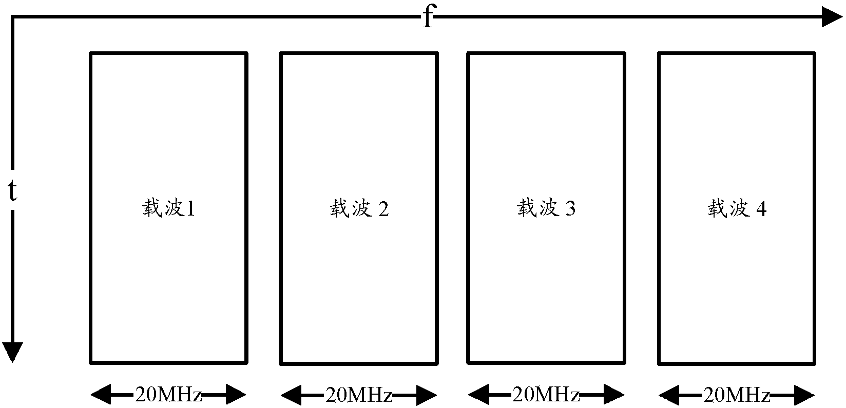
technical field [0001] The present invention relates to the technical field of wireless communication, in particular to a downlink user-specific DM-RS transmission method, a UE and a network side device. Background technique [0002] 1) CA introduction in LTE-A [0003] In order to meet the peak rate requirements in the LTE-A (Long Term Evolution-Advance, Long Term Evolution Enhancement) system, Carrier Aggregation (CA, Carrier Aggregation) technology is introduced, that is, multiple continuous or discontinuous carriers under the same base station eNB Aggregate together and serve UE at the same time, such as figure 1 shown. These aggregated carriers are also called component carriers (CC, Component Carrier). The carrier used by each cell may be a component carrier. In order to ensure backward compatibility with the LTE system, each component carrier does not exceed 20MHz. [0004] 2) Introduction of DM-RS in LTE-A system [0005] Nine downlink transmission modes are de...

Claims


Application Information

Patent Timeline
Patent Type & Authority Applications(China)
IPC IPC(8): H04W28/16H04W72/04
CPCH04L5/0023H04L5/001H04L5/0016H04L5/0051H04W28/06H04W72/00
Inventor 高雪娟丁昱
Owner DATANG MOBILE COMM EQUIP CO LTD
Why Eureka
Try Eureka