

LED constant-current driver overvoltage and overcurrent protection module
A technology of overvoltage and overcurrent protection and constant current driver, which is applied to emergency protection circuit devices for limiting overcurrent/overvoltage, emergency protection circuit devices, lighting devices, etc., and can solve constant current drive damage and fuse overvoltage Protection is not obvious and other problems, to achieve the effect of protection safety
Inactive Publication Date: 2014-01-15
JIANGSU SMILE OPTOELECTRONICS TECH
View PDF0 Cites 1 Cited by
- Summary
- Abstract
- Description
- Claims
- Application Information
AI Technical Summary
Problems solved by technology
[0002] At present, the current regulators on the market strictly distinguish the positive and negative plates of the input terminal. If the positive and negative poles are reversed during the construction process, the constant current drive will be damaged. Second, most of the current controllers on the market are protected by fuses. This method, this method has a certain protection delay due to the fuse, and the fuse is not obvious to the overvoltage protection
Method used
View moreImage
Smart ImageViewing Examples

Examples
Embodiment Construction
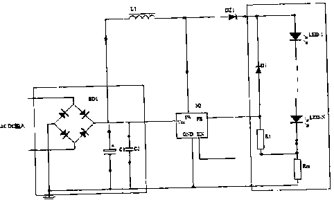
[0007] The overvoltage and overcurrent protection module of the LED constant current driver is arranged between the driver and the load, and the protection module includes an overvoltage diode D1, resistors R1 and Rcs.
Login to View More PUM
 Abstract
The invention relates to an LED constant-current driver overvoltage and overcurrent protection module. The protection module is arranged between a driver and a load. The protection module comprises an overvoltage diode D1 and resistors R1 and Rcs. The output part is protected by the use of the overvoltage diode D1. If an output voltage of a galvanostat is too high (higher than a voltage regulation value of D1), the output voltage will be limited at the voltage regulation value of D1 so as to prevent LED damage caused by overvoltage. According to the output part, the resistor Rcs is used as a current limiting resistor of an output load. If output current exceeds service power of the resistor, the resistor will protect safety of LED due to insufficient power.
Description
technical field [0001] The invention relates to a constant current driver, in particular to an LED constant current driver overvoltage and overcurrent protection module. Background technique [0002] At present, the current regulators on the market strictly distinguish the positive and negative plates of the input terminal. If the positive and negative poles are reversed during the construction process, the constant current drive will be damaged. Second, most of the current controllers on the market are protected by fuses. This method, this method has a certain protection delay due to the fuse, and the fuse is not obvious for overvoltage protection. Contents of the invention [0003] In order to solve the above problems, the present invention provides an LED constant current driver overvoltage and overcurrent protection module with simple structure, stable operation and LED safety protection. [0004] The technical solution of the present invention is: the protection modu...
Claims
Login to View More Application Information
Patent Timeline
 Patent Type & AuthorityApplications(China)
IPC IPC(8): H05B37/02H02H9/04H02H9/02
Inventor夏平中雍冬梅
OwnerJIANGSU SMILE OPTOELECTRONICS TECH