Vacuum thermal bonding device and vacuum thermal bonding method

A vacuum heating and bonding device technology, applied in lamination devices, chemical instruments and methods, sustainable manufacturing/processing, etc., can solve problems such as poor sealing, difficult-to-seal bonding, and damaged sealing corners

Active Publication Date: 2014-01-15
MIKADO TECHNOS
View PDF5 Cites 20 Cited by
  • Summary
  • Abstract
  • Description
  • Claims
  • Application Information

AI Technical Summary

Problems solved by technology

However, contrary to expectations, it is difficult to bond or seal components well to the substrate while minimizing adhesive spillage
In addition, when using a sealing sheet to seal and bond components to a pre-adhesively fixed substrate with components, it is difficult to seal and join with a uniform thickness, and there are cases where the seal corners are damaged and poor sealing occurs.

Method used


Image

  • Vacuum thermal bonding device and vacuum thermal bonding method
  • Vacuum thermal bonding device and vacuum thermal bonding method
  • Vacuum thermal bonding device and vacuum thermal bonding method

Examples


no. 1 approach )

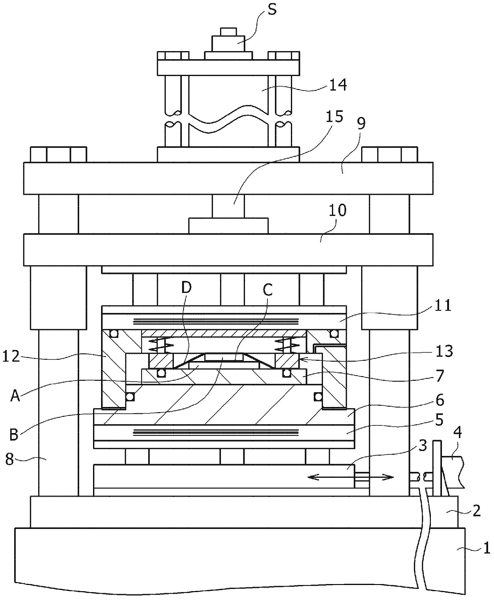
[0109] figure 1 The vacuum heating bonding apparatus of the present invention according to the first embodiment is shown in . In this vacuum heating bonding apparatus, a pressurized cylinder lower plate 2 is arranged on the base 1, and a slide movable table 3 is arranged on the pressurized cylinder lower plate 2. The heated joint moves in and out. A lower heating plate 5 is thermally insulated above the sliding table 3 , a lower plate member 6 is arranged on the upper surface of the lower heating plate 5 , and a substrate mounting table 7 is placed on the upper surface of the lower plate member.

[0110] A plurality of struts 8 are arranged vertically on the pressurizing cylinder lower plate 2 , and a pressurizing cylinder upper plate 9 is fixed to the upper ends of the struts 8 . The pillar 8 can also be directly arranged vertically on the abutment 1 . Below the upper plate 9 of the pressurizing cylinder, an intermediate moving member (intermediate member) 10 is arranged s...


PUM

PropertyMeasurementUnit
thicknessaaaaaaaaaa

Abstract

In the present invention, minute pressing force adjustments are enabled while preventing air from entering an adhesion layer in a vacuum so as to prevent running off of an adhesive as much as possible under a moderate pressure in order to form an adhesion layer with an appropriate thickness, and a device is bonded to a substrate by means of vacuum thermal bonding. With this vacuum thermal bonding device, a drive unit causes the bottom section of a top frame member to slide to airtightly seal the periphery of a bottom plate member so as to form a vacuum partition therein, a pressure release film is brought into contact with the top surface of a device and softened by applying heat under atmospheric pressure, a vacuum chamber is evacuated, the periphery of the pressure release film is held airtightly between the top surface of a substrate mount of the bottom plate member and the bottom surface of an internal frame body by moving the bottom plate member and an intermediary member closer relative to each other, and atmospheric pressure or a pressure higher than atmospheric pressure is applied to a space formed above the pressure release film in the vacuum chamber so as to cause the pressure release film to tightly adhere to the outer surfaces of the substrate and the device in order to bond the device to the substrate.

Description

technical field [0001] The present invention relates to a vacuum heating bonding device and a vacuum heating bonding method, which are used for bonding components such as semiconductors, resistors and / or capacitors on a substrate, or bonding the above substrate and a heat dissipation plate, and transferring imprints (Japanese: イン プリント転), or bonding or molding ITO films and other diaphragms. Background technique [0002] When bonding or sealing elements such as semiconductors, resistors, and / or capacitors on a substrate, an insulating adhesive or a conductive adhesive is used for bonding between the substrate and the element depending on the purpose. When bonding, if the adhesive layer is pressurized with strong pressure, the adhesive will overflow, and the formed insulating layer or conductive layer will have insufficient bonding capacity and performance will be deteriorated. [0003] The present applicant proposes a hot press processing device for a thin-plate-shaped workpi...

Claims


Application Information

Patent Timeline
Patent Type & Authority Applications(China)
IPC IPC(8): H01L21/56B29C65/48B30B15/34
CPCH01L24/32H01L24/75H01L24/83H01L2224/32225H01L2224/75102H01L2224/75315H01L2224/75316H01L2224/83001H01L2224/83203B30B5/02B30B11/027B30B15/34B32B37/1009B32B37/1284B32B2457/12B32B2457/14H01L2224/2929H01L2224/293H01L2224/75101H01L2224/75317H01L2224/8309H01L2224/83191H01L2224/83209H01L2924/07802H05K3/305Y10T29/53174Y10T29/53191Y02P70/50H01L2924/00014H01L2924/00
Inventor 伊藤隆志佐藤丰树
Owner MIKADO TECHNOS
Why Eureka
Try Eureka