
Clamping type buckling element zipper of impervious structure

A technology for fastening components and zippers, applied in the direction of sliding fastener components, fasteners, applications, etc., can solve the problems of loss of waterproof function, complicated process, deformation of elastic waterproof colloid, etc., to achieve the function of preventing fluid penetration and durability, expand Application range, friction reduction effect

Inactive Publication Date: 2014-01-22
周朝木
View PDF17 Cites 2 Cited by
  • Summary
  • Abstract
  • Description
  • Claims
  • Application Information

AI Technical Summary

Problems solved by technology

However, the waterproof colloid does not have a strong combination with the fastening elements. In addition to being not durable, it requires a special-shaped zipper puller to pull it together, and the special zipper puller often causes the fastening elements to be arranged and occluded. Reduce the scope of use of the waterproof zipper
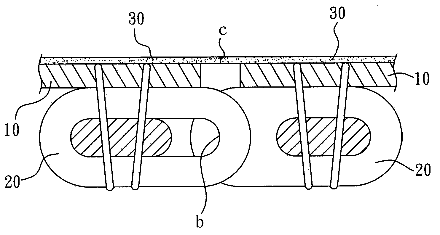
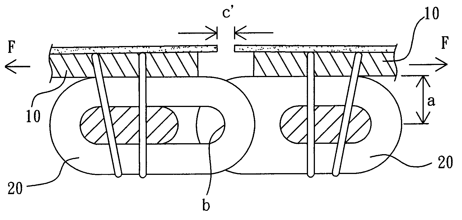
[0009] Furthermore, as disclosed in U.S. Patent No. 2,557,163, when the two rows of fastening elements are separated, waterproof colloids are formed on the inner edge of the supporting cloth in a discontinuous manner, and the fastening elements are combined to form a waterproof zipper. The fastening components have different shapes, so they must be molded and assembled separately. The obvious defect of this case is that, in addition to the complicated process and difficult construction, the combination of the waterproof colloid and the fastening components does not use adhesives Therefore, the contact surfaces of the two cannot be completely tightly combined, so that the lateral force will deform the elastic waterproof colloid, and create a gap with the lateral side of the fastening element, so that the fluid will seep through it and lose the waterproof function

Method used


Image

  • Clamping type buckling element zipper of impervious structure
  • Clamping type buckling element zipper of impervious structure
  • Clamping type buckling element zipper of impervious structure

Examples


Embodiment Construction

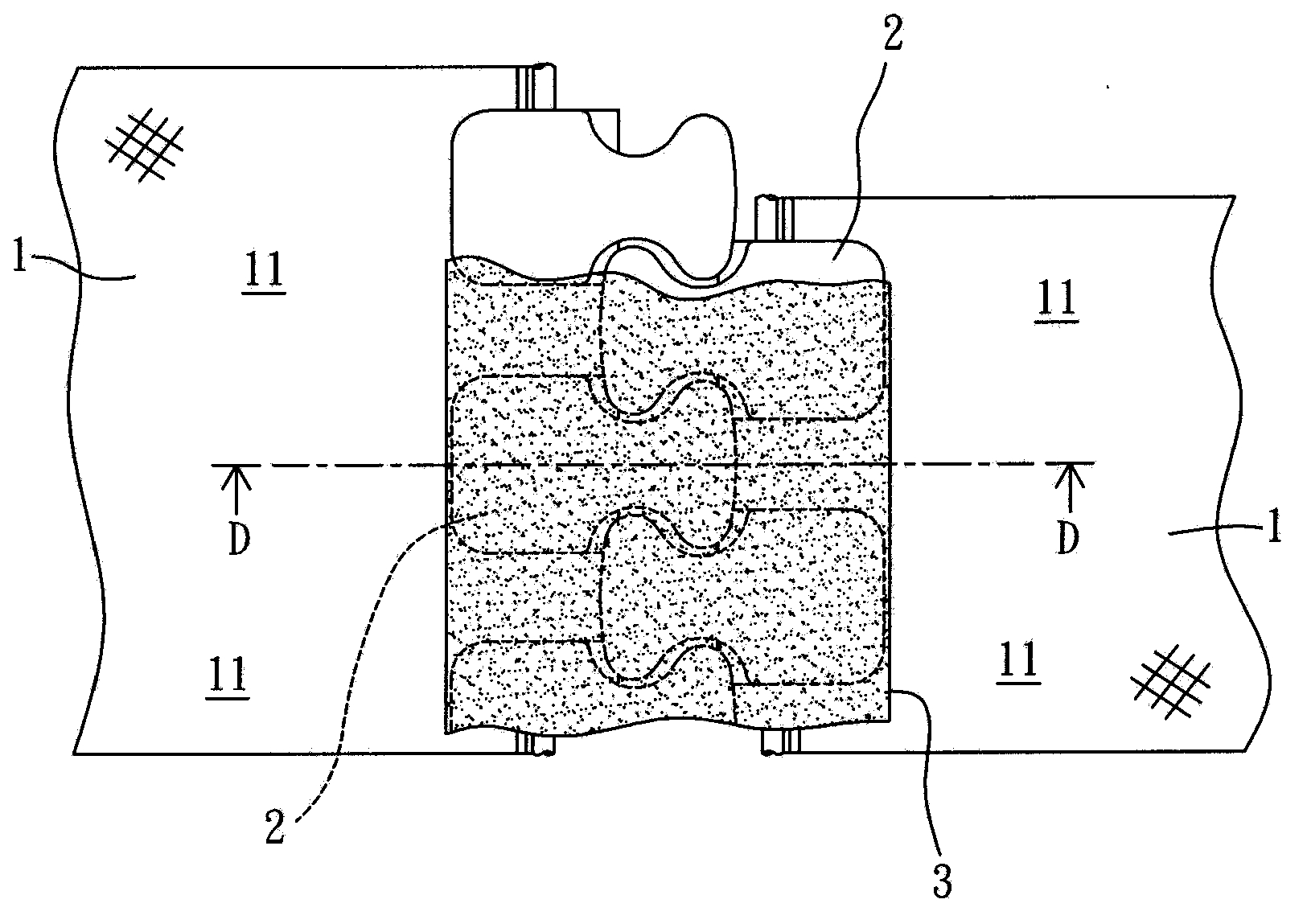
[0031] Such as Figure 3 to Figure 6As shown, basically, the clip-type fastening element zipper with anti-seepage structure of the present invention includes a pair of left-right symmetrical support tapes 1, two rows of fastening elements 2 that are arranged in parallel and are staggered and spaced apart from each other, and anti-seepage glue Composed of 3.

[0032] The pair of support tapes 1 is made of warp knitting or weaving. If necessary, one of the warp or weft directions must be made of elastic tissue, so that the warp or weft directions of the support tape 1 have stretch elasticity. . Wherein, the pair of support tapes 1 have first and second surfaces 11 and 12 respectively, and the fastening element 2 sandwiches the inner edges of the first and second surfaces 11 and 12 of each support tape 1 in a sandwich manner.

[0033] The fastening element 2 may be implemented by plastic injection molding or metal riveting, or as Image 6 As shown, the fastening element 2 is a...


PUM


Abstract

The invention discloses a clamping type buckling element zipper of an impervious structure. The clamping type buckling element zipper comprises a pair of supporting cloth belts which are arrayed parallelly and laterally, two rows of clamping type buckling elements and an impervious rubber body. The two rows of clamping type buckling elements are respectively arranged on the inner edge of the first face and the inner edge of the second face of each supporting cloth belt. The impervious rubber body continually covers at least one face of the two rows of buckling elements so as to form a cover surface layer when the two rows of the buckling elements are in a buckling state, and is simultaneously injected into the interior gap of the two rows of buckling elements and the supporting cloth belts and the other face gap of the two rows of buckling elements so as to respectively form a gap filling part and an extending part. The impervious rubber body is divided from the middle of the two rows of buckling elements of the supporting cloth belts so as to enable the zipper to be buckled or separated.

Description

technical field [0001] The invention relates to a zipper with an anti-seepage structure, in particular to a clip-type fastening element zipper with an anti-seepage structure. Background technique [0002] According to the known waterproof zipper, it is distinguished by the type of fastening element, which generally belongs to two categories: single-sided fastening element zipper and clip-type fastening element zipper. The former is the known nylon zipper, and its fastening element is Thick man-made fiber monofilament is heated and shaped into a spiral continuous fastening element, and then combined with one side of the inner edge of the supporting cloth belt by sewing or weaving; the latter clip-type fastening element zipper has a relatively strong Diversified tooth types, materials and processing methods are combined with the support belt, such as known metal zippers, plastic steel zippers, L-type nylon zippers, etc., which are characterized in that the fastening elements c...

Claims


Application Information

Patent Timeline
Patent Type & Authority Applications(China)
IPC IPC(8): A44B19/32
Inventor 周朝木
Owner 周朝木
Learn More