Cooling mechanism and ultrasonic probe

A technology for cooling mechanisms and ultrasonic probes, applied in catheters, surgery, etc., can solve the problem of increasing the diagnosis time of multi-plane ultrasonic probes, not being able to apply transducer units to multi-plane ultrasonic probes, and thermal conductivity that cannot meet the heat dissipation requirements of multi-plane ultrasonic probes, etc. problem, to achieve the effect of improving comfort and reducing physiological burden

Active Publication Date: 2014-01-22
SONOSCAPE MEDICAL CORP
View PDF9 Cites 6 Cited by
  • Summary
  • Abstract
  • Description
  • Claims
  • Application Information

AI Technical Summary

Problems solved by technology

[0004] However, the above as figure 2 In the first technical solution shown, the heat dissipation unit needs to be in direct contact with the transducer unit, that is, there cannot be relative positional movement between the transducer unit and the heat dissipation unit. This limitation makes this technical solution not suitable for energy conversion A multi-plane ultrasonic probe whose unit can rotate; in the second technical solution above, the thermal conductivity of the silicone grease cannot meet the heat dissipation requirements of the continuous use of the multi-plane ultrasonic probe: the temperature of the insertion part of the multi-plane ultrasonic probe will increase with the power-on time. Requires shutdown to cool down when temperature reaches threshold, thus increasing diagnostic time with multiplanar ultrasound probes and placing additional physiological burden on the subject

Method used


Image

  • Cooling mechanism and ultrasonic probe
  • Cooling mechanism and ultrasonic probe
  • Cooling mechanism and ultrasonic probe

Examples


Embodiment Construction

[0028] The technical solutions in the invention will be clearly and completely described below in conjunction with the description and drawings of the invention. Obviously, the described embodiments are only some of the embodiments of the present invention, not all of them. Based on the embodiments of the present invention, all other embodiments obtained by persons of ordinary skill in the art without making creative efforts belong to the protection scope of the present invention. The first embodiment of the present invention will describe a cooling mechanism in detail. The cooling mechanism described in this embodiment can be applied to a multi-plane ultrasonic probe, and the cooling mechanism is arranged in the insertion portion of the multi-plane ultrasonic probe.

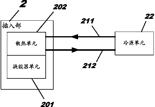
[0029] See image 3 The insertion part 3 of the multi-plane ultrasonic probe includes: a cooling mechanism 30 , an outer protective shell 31 , a transducer unit 32 and a rotating mechanism 33 for rotating the tr...


PUM


Abstract

The invention provides a cooling mechanism and an ultrasonic probe. The cooling mechanism is used for dissipating heat of the multi-plane ultrasonic probe. According to the technical scheme, the cooling mechanism is arranged inside the ultrasonic probe and comprises a refrigerant feeding pipe, a refrigerant exhaust pipe and a sealing baffle. The sealing baffle is connected with an outer protective shell in a sealing mode to form a sealing cavity which is used for containing an energy converter unit and part of a revolving mechanism. A first through hole, a second through hole and a third through hole are formed in the sealing baffle, wherein the third through hole allows the revolving mechanism to penetrate through. The refrigerant feeding pipe is connected with the first through hole in a sealing mode, the refrigerant exhaust pipe is connected with the second through hole in a sealing mode, the refrigerant feeding pipe is used for feeding refrigerant to the sealing cavity, and the refrigerant exhaust pipe is used for exhausting the refrigerant out of the sealing cavity. By the implementation of the technical scheme, the multi-plane ultrasonic probe in a working state can be effectively cooled, and the working temperature of the multi-plane ultrasonic probe is controlled at about 37 DEG C which is about the same as the temperature of the human body.

Description

technical field [0001] The invention relates to the technical field of ultrasonic diagnostic instruments, in particular to a cooling mechanism and an ultrasonic probe. Background technique [0002] Ultrasonic Probe is an ultrasonic diagnostic instrument that inserts the transducer unit into the body cavity of the subject. Please refer to figure 1 , the transducer unit 110 is located in the insertion part 11, the insertion part 11 is used to be inserted into the cavity of the subject, and the grip part 12 is used to be held by an operator outside the cavity. When the transducer unit 110 is working, a large amount of heat is generated so that the temperature of the insertion part 11 rises. If the heat dissipation is not timely, the transducer unit 110 will be damaged or discomfort in the body cavity of the subject will be caused. [0003] Currently, one way to dissipate heat is through a liquid cooling system, see figure 2 , there is a transducer unit 201 and a heat dissipa...

Claims


Application Information

Patent Timeline
Patent Type & Authority Applications(China)
IPC IPC(8): A61B8/12
Inventor 孙强周曙光叶高山陈雄
Owner SONOSCAPE MEDICAL CORP
Why Eureka
Try Eureka