Panel structure of electromagnetic heating device

A technology for heating appliances and panels, applied in electric heating fuel, lighting and heating equipment, household heating, etc., can solve the problem of temperature control of the upper pot without considering the thermal influence of the curved ceramic panel, panel heat dissipation, induction cooker long work issues

Inactive Publication Date: 2009-09-09
FOSHAN FUSHIBAO ELECTRICAL APPLIANCE TECH
View PDF1 Cites 5 Cited by
  • Summary
  • Abstract
  • Description
  • Claims
  • Application Information

AI Technical Summary

Problems solved by technology

Through the analysis of the above technical solution, it can be found that the technical solution does not consider the thermal influence of the high temperature of the cooking pot on the curved ceramic panel and the heat dissipation of the panel itself, nor does it consider the temperature control of the upper pot, resulting in the use of The induction cooker manufactured by this technology not only cannot work continuously for a relatively long time, but also the heating area of ​​the pot is too small, the taste of cooking is very poor, and the cooked objects in the pot cannot be effectively controlled, resulting in burning problems; Secondly, we have to use expensive high-temperature-resistant panels such as microcrystalline panels, but at present, the domestic production of concave arc-shaped microcrystalline panels has not been effectively solved. Not only is the supply very small, but all rely on imports; Shaped panels, due to the small thermal expansion coefficient of ceramic materials, high temperature is easy to crack
Therefore, after the disclosure of the above-mentioned technical invention, it has not been effectively applied so far.

Method used


Image

  • Panel structure of electromagnetic heating device
  • Panel structure of electromagnetic heating device
  • Panel structure of electromagnetic heating device

Examples


Embodiment 1

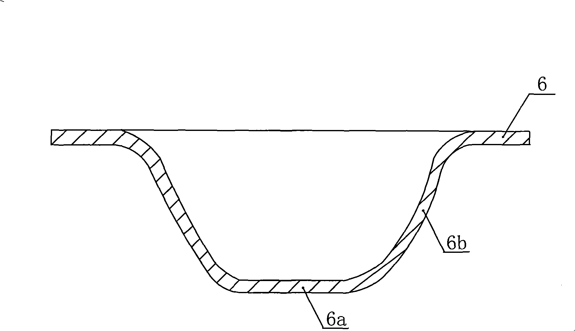
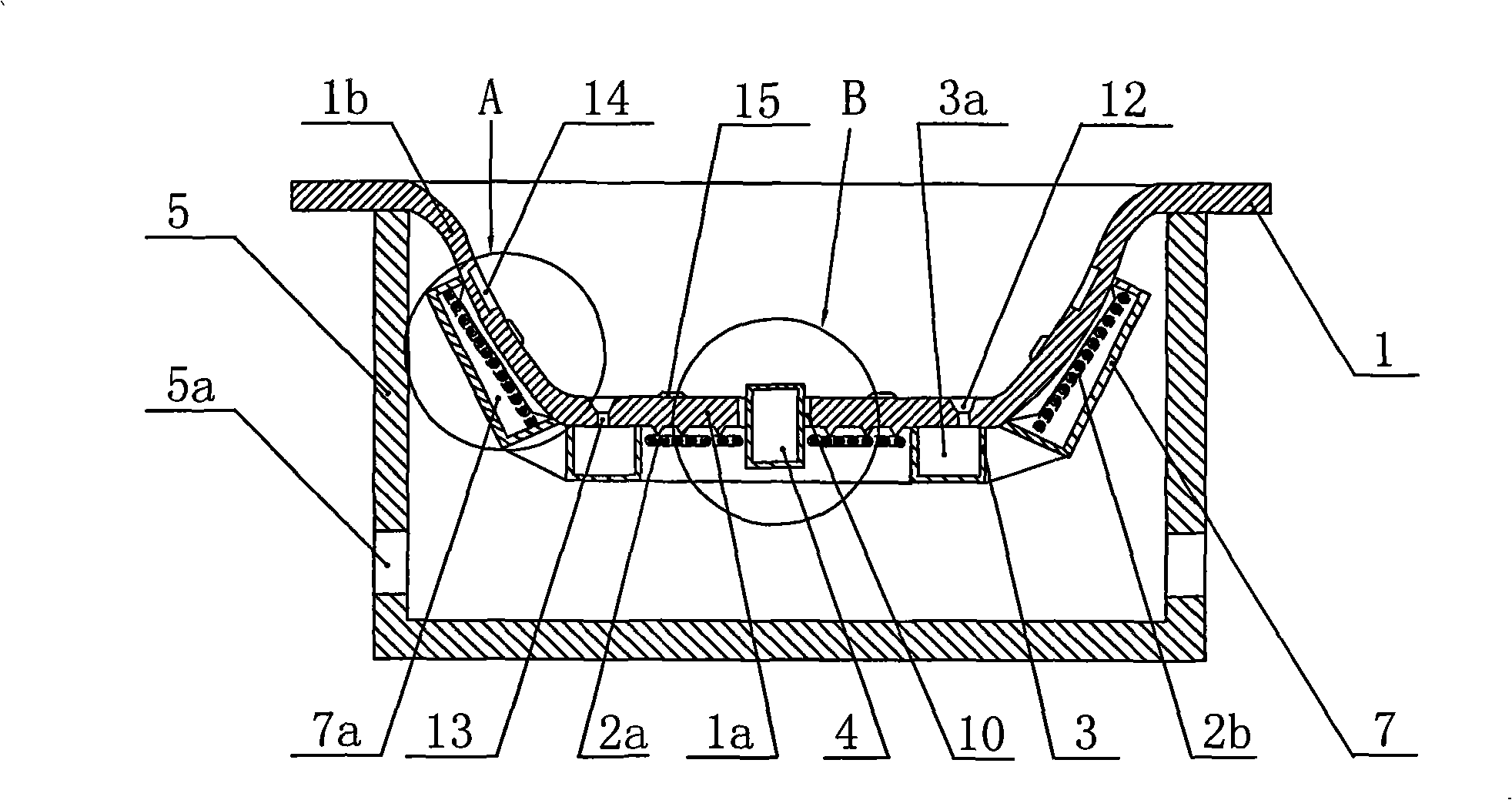
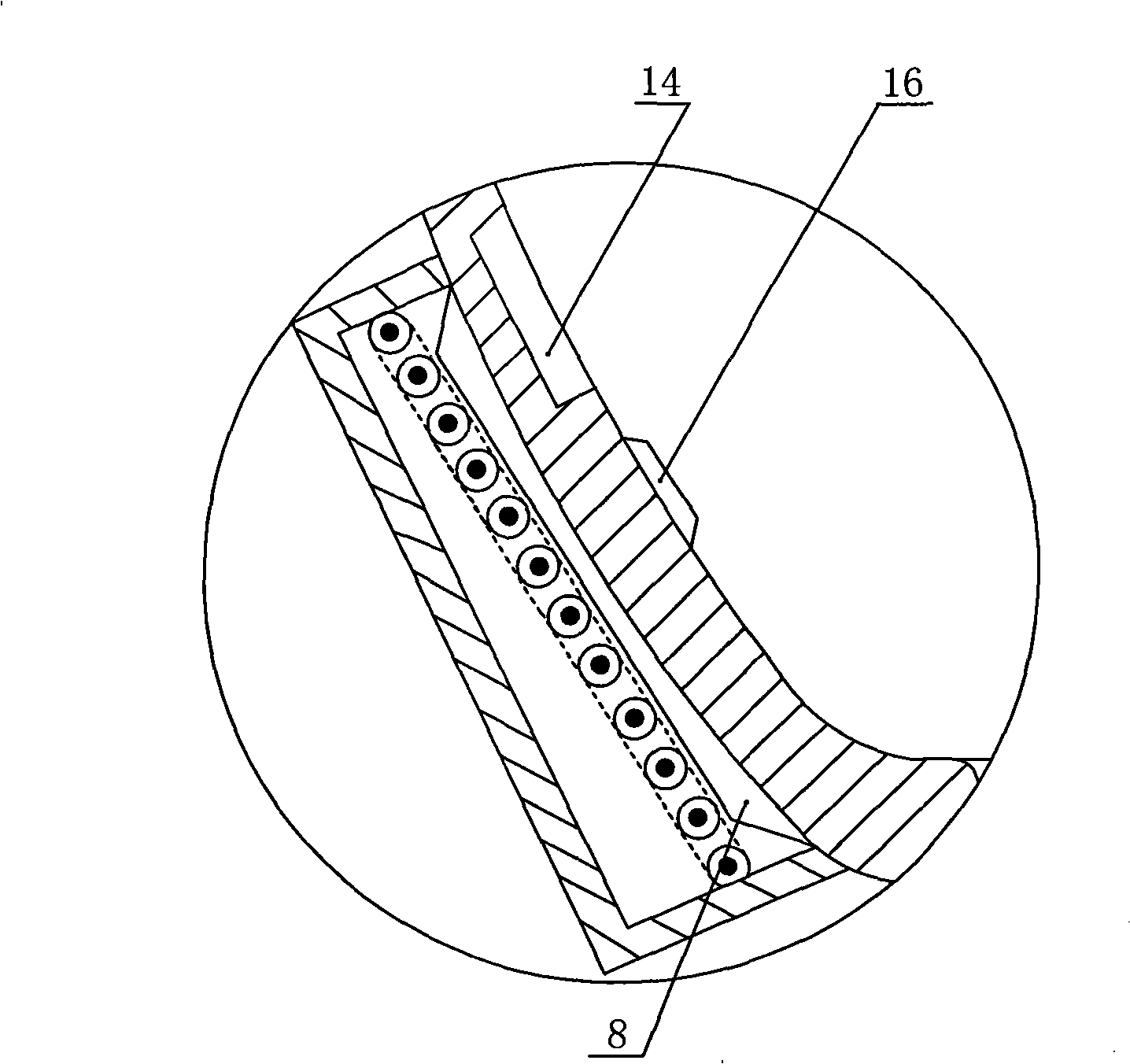
[0048] Such as figure 1 , figure 2 As shown, a new type of electromagnetic heating appliance includes a panel 1 and a housing 5 supporting the panel 1, wherein the panel 1 is made of temperature-resistant and magnetically permeable plastic. Parts such as control system and fan are accommodated in the housing 5; the side wall of the housing 5 is provided with an air inlet 5a, and a forced air fan (not shown in the figure) can also be set at the air inlet 5a position. out). The panel 1 has a concave arc shape, and the panel 1 includes a substantially flat bottom wall 1a and a side wall 1b surrounding the bottom wall 1a to form a concave arc panel, wherein the bottom wall 1a Constitute the bottom area of ​​the panel 1; a temperature sensor installation hole 10 is provided at the center of the bottom wall 1a, and a temperature sensor 4 that can be electrically connected to the control system of the electromagnetic heating appliance is arranged in the temperature sensor installa...

Embodiment 2

[0061] Such as Figure 7 , Figure 8 As shown, the difference from Embodiment 1 is that the panel 1 is in a concave arc shape, and the panel 1 includes a bottom wall portion 1a which is basically a small concave arc shape and a concave arc-shaped panel formed around the bottom wall portion 1a The side wall portion 1b; wherein the small concave arc-shaped bottom wall portion 1a is in a gradually (gradually) concave shape downward, and the center position of the bottom wall portion 1a is basically at the lowest point of the bottom wall portion 1a Point, the concave arc diameter R1 of the bottom wall portion 1a is larger than the concave arc diameter R2 of the side wall portion 1b.

[0062] Such as Figure 9 As shown, as an equivalent implementation structure of the bottom wall portion 1a, wherein the small concave arc-shaped bottom wall portion 1a is in a gradually (gradually) convex shape, and the center position of the bottom wall portion 1a It is basically at the highest p...


PUM


Abstract

The invention relates to a panel structure of an electromagnetic heating device, comprising a concave arc panel and an electromagnetic coil arranged at the outer side of the panel; the panel comprises a bottom wall part and a side wall part surrounding the bottom wall part and forming the concave arc panel; the center of the bottom wall part is provided with a vent hole and a temperature sensor; and the inner side wall of the panel is symmetrically provided with a cookware positioning boss. More than three radial convex bars are uniformly arranged along the outer side wall of the panel, and the electromagnetic coil is tightly clung and fixedly connected with the top parts of the radial convex bars; a first electromagnetic coil is correspondingly arranged at the bottom wall part; a second electromagnetic coil is correspondingly arranged at the side wall part; and the second coil is arc-shaped and is matched with the outer side wall of the side wall part. A ring-shaped bottom groove is arranged at the inner side of the panel and positioned at the joint of the bottom wall part and the side wall part; and more than one vent hole which penetrates through the panel is arranged in the bottom groove. Due to the advantages, the panel structure can be widely applied in electrical appliances using the electromagnetic heating device, in particularly to an electromagnetic oven product used for cooking dishes.

Description

technical field [0001] The invention relates to an electromagnetic heating appliance, in particular to a panel structure with a curved panel for the electromagnetic heating appliance. Background technique [0002] The arc-shaped panel structure of the existing electromagnetic heating appliance is more typically disclosed on November 10, 1999, and the name is called the ZL98241610.5 utility model patent of "an electromagnetic cooker coil that is especially suitable for a frying pan". This patent discloses that a coil for passing current is provided inside the induction cooker, and an arc-shaped ceramic panel is arranged above the coil, and an arc-shaped pot can be placed on the top of the panel; the feature is that the coil is matched with the pot The arc shape extends from the inside to the outside to form a concave arc surface, so that each part of the coil maintains the same distance from the upper ceramic panel and the arc-shaped pot. The coil of the utility model can co...

Claims


Application Information

Patent Timeline
Patent Type & Authority Applications(China)
IPC IPC(8): F24C15/10F24C7/06
Inventor 陆社本刘翔高
Owner FOSHAN FUSHIBAO ELECTRICAL APPLIANCE TECH
Why Eureka
Try Eureka