Temperature control method, device and equipment of memory and storage medium

A memory and temperature control technology, applied in instruments, climate sustainability, computing, etc., can solve problems such as inability to control the working temperature of solid-state hard disks, temperature control lag, and large time overhead

Active Publication Date: 2020-11-17
SHENZHEN DAPU MICROELECTRONICS CO LTD
View PDF18 Cites 4 Cited by
  • Summary
  • Abstract
  • Description
  • Claims
  • Application Information

AI Technical Summary

Problems solved by technology

[0004] This method has certain disadvantages, the change of the clock frequency between the master control of the SSD and the flash memory needs to be completed in an idle state
The idle state first needs to wait for the command being executed to complete before entering, and the time overhead is relatively large.
In addition, the master needs to send commands to the flash memory to complete the clock frequency switching, which will also bring a certain amount of time overhead
That is to say, the traditional method has the problem of temperature control lag, and cannot control the working temperature of the solid-state hard disk in time, which easily affects the normal operation of electronic products.

Method used


Image

  • Temperature control method, device and equipment of memory and storage medium
  • Temperature control method, device and equipment of memory and storage medium
  • Temperature control method, device and equipment of memory and storage medium

Examples


Embodiment Construction

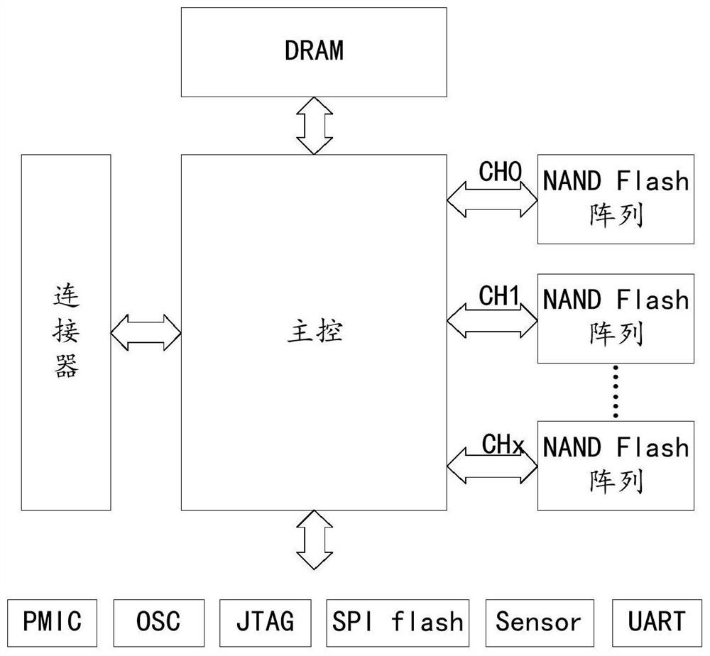
[0053] The core of the present application is to provide a method for temperature control of a memory, and the memory may be a solid-state hard disk or the like. For ease of understanding, before describing the solution of the present application, the composition and structure of the solid-state hard disk will be described first.

[0054] figure 2 Shown is a schematic diagram of the composition and structure of a typical solid-state hard drive. Such as figure 2 As shown, the solid-state hard disk can include a main control (Controller), a NAND Flash array (NAND Flash Array), a DRAM (Dynamic Random Access Memory, dynamic random access memory) and other peripheral units, such as a PMIC (Power Management IC, a power management integrated circuit ), OSC (Open Source Commerce, open source commercial software), JTAG (Joint TestAction Group, joint test working group), SPI flash (using SPI (Serial Peripheral Interface, serial peripheral device interface) communication flash memory...


PUM


Abstract

The invention discloses a temperature control method of a memory. The method comprises the following steps: monitoring the working temperature of the memory; according to the working temperature of the memory and a preset temperature threshold, determining whether a preset temperature control triggering condition is reached currently; if yes, inquiring a strategy table according to the working temperature of the memory, and determining a target temperature control adjustment strategy wherein the strategy table comprises multiple levels of temperature control adjustment strategies; and controlling the working temperature of the memory by using the target temperature control adjustment strategy. By applying the technical scheme provided by the embodiment of the invention, the strategy tablecomprises multiple levels of temperature control adjustment strategies. According to the working temperature of the memory, a proper target adjustment strategy is obtained by inquiring the strategy table, frequency switching is not needed, the working temperature of the memory can be effectively controlled in time, and normal operation of an electronic product is prevented from being influenced. The invention further discloses a temperature control device and equipment of the memory and a storage medium, and the temperature control device and equipment have corresponding technical effects.

Description

technical field [0001] The present application relates to the technical field of computer applications, and in particular to a memory temperature control method, device, equipment and storage medium. Background technique [0002] At present, storage devices such as solid state disks (Solid State Disk or Solid State Drive, SSD for short) are more and more commonly used in electronic products such as computers and servers. The solid-state hard disk has a certain operating temperature range, and the normal operation of electronic products can only be guaranteed if the operating temperature is within this operating temperature range. During the working process of electronic products, when the ambient temperature rises and the workload increases, the operating temperature of the solid-state hard disk tends to exceed its operating temperature range. In this case, it is generally necessary to reduce the operating power consumption to achieve the purpose of cooling. [0003] Flash ...

Claims


Application Information

Patent Timeline
Patent Type & Authority Applications(China)
IPC IPC(8): G06F1/20
CPCG06F1/206Y02D10/00
Inventor 方浩俊印中举陆震熙黄运新杨亚飞
Owner SHENZHEN DAPU MICROELECTRONICS CO LTD
Why Eureka
Try Eureka