
Roof Steering Follow-up Air Resistance Retarder

A technology of air resistance and retarder, which is applied in the direction of brakes, brake components, vehicle parts, etc., can solve the problems of not conforming to the work of auxiliary brakes, affecting the driver's braking feeling, and weakening the effect of retarding brakes, etc., to achieve improved Anti-heat decay performance, ideal effect, effect with little influence

Active Publication Date: 2015-11-18
JIANGSU UNIV OF TECH
View PDF6 Cites 0 Cited by
  • Summary
  • Abstract
  • Description
  • Claims
  • Application Information

AI Technical Summary

Problems solved by technology

However, this invention patent is mainly aimed at the braking situation of the motor vehicle. The deceleration plate only participates in the work when the brake pedal travels more than half or when the brake pedal is stepped on rapidly, which does not meet the requirements of the auxiliary brake when the passenger car slows down; The body steel plate is used as the deceleration plate, the hydraulic telescopic strut is installed at the inclined beam of the "C-pillar" of the frame, and its transmission system is not suitable for installation and use on passenger cars.
Moreover, when the passenger car goes downhill continuously and brakes at a slow speed, if there is a certain curvature in the road, the air resistance plate of the traditional fixed connection method is not aligned with the driving direction of the passenger car, and its slow braking effect will be weakened, and the Affect the driver's braking feeling
So far, there has been little mention of a passenger car roof air resistance retarding brake device with steering follow-up function

Method used


Image

  • Roof Steering Follow-up Air Resistance Retarder
  • Roof Steering Follow-up Air Resistance Retarder
  • Roof Steering Follow-up Air Resistance Retarder

Examples


Embodiment Construction

[0035] In order to make the content of the present invention more clearly understood, the present invention will be further described in detail below based on specific embodiments and in conjunction with the accompanying drawings.

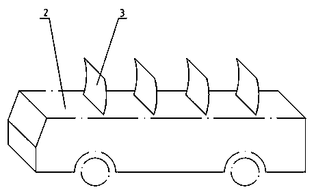
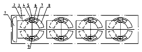
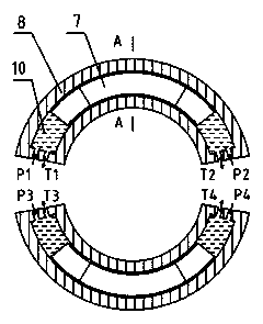
[0036] Such as Figure 1-8 As shown, a roof steering follow-up air resistance slowing device, it includes a fixed bracket and at least one slowing sub-device; the fixed bracket is installed on the roof 2, and the slowing sub-device includes:

[0037] A wind-blocking blade 3;

[0038] One is used to make the choke blade 3 rotate vertically relative to the roof 2 and is installed on the steering follower mechanism on the fixed bracket;

[0039] A transmission mechanism for making the choke blade 3 swing horizontally relative to the roof 2 and installed on the steering follow-up mechanism, the transmission mechanism includes a rotating shaft 5-1 and a motor 4, and the rotating shaft 5-1 is rotatably supported on On the steering follower mechanism, t...


PUM


Abstract

The invention discloses a roof steering follow-up air resistance retarder comprising a control system, a fixed support and at least one sub-retarder. Each sub-retarder comprises a wind resisting blade, a steering follow-up mechanism, a transmission mechanism and a locking mechanism, wherein the steering follow-up mechanism is used for driving the wind resisting blade to perpendicularly rotate in relation to a car roof and mounted on the fixed support, the transmission mechanism is used for driving the wind resisting blade to horizontally swing in relation to the car roof and mounted on the steering follow-up mechanism, the transmission mechanism comprises rotating shafts and a motor, the rotating shafts are rotatably supported on the steering follow-up mechanism, the motor is movably connected with the rotating shafts, one wind resisting blade is fixedly connected to each rotating shaft, the locking mechanism disposed on the rotating shafts is used for limiting the swing angles of the rotating shafts which horizontally swing in relation to the car roof. The roof steering follow-up air resistance retarder has the advantages that the roof steering follow-up air resistance retarder has the steering follow-up function, a car is retarded by means of air resistance, thermal load of a frictional brake during vehicle continuous braking and continuous downhill running is distributed effectively, heat fading is prevented, vehicle driving safety is improved, and wear of the frictional brake is reduced.

Description

technical field [0001] The invention relates to a roof steering follow-up air resistance slowing device, which belongs to the field of vehicle auxiliary braking. Background technique [0002] The braking system is one of the important components of the vehicle, which is directly related to the safety of life and property, including service brakes, parking brakes and auxiliary brakes. The service brake is the main brake of the vehicle, and generally adopts drum or disc friction braking method, which converts the kinetic energy and potential energy of the vehicle into heat energy through friction, so as to realize the purpose of deceleration or braking of the vehicle. [0003] With the advancement of vehicle technology and the improvement of road conditions, passenger cars, like other commercial vehicles, are developing towards the direction of optimizing the operating efficiency of high speed and heavy load. Since the kinetic energy of a vehicle is proportional to the square ...

Claims


Application Information

Patent Timeline
Patent Type & Authority Patents(China)
IPC IPC(8): B60T1/16
Inventor 王奎洋贝绍轶李国庆唐金花
Owner JIANGSU UNIV OF TECH
Learn More