Double-cylinder compression packer

A compression packer and hydraulic cylinder technology, which is used in sealing/packing, wellbore/well components, earth-moving drilling, etc. Peristalsis and other problems, to achieve the effect of prolonging the service life, uniform sealing pressure, and increasing sealing pressure

Active Publication Date: 2014-01-22
齐齐哈尔亚盛机械制造有限公司
View PDF6 Cites 8 Cited by
  • Summary
  • Abstract
  • Description
  • Claims
  • Application Information

AI Technical Summary

Problems solved by technology

The currently used hydraulic packer has a long rubber tube, and after the packer is set, the shoulder of the rubber tube protrudes seriously, causing the shoulder of the rubber tube to rupture due to stress concentration, so the sealing pressure of the rubber tube is low and the service life is not long , the packing effect of the packer is not good
[0003] After the packer is set, due to the complex force of the packer, it is easy to cause the packer rubber tube to wriggle and cause the packer to lose its sealing effect

Method used


Image

  • Double-cylinder compression packer
  • Double-cylinder compression packer
  • Double-cylinder compression packer

Examples


Embodiment Construction

[0027] The present invention will be further described below in combination with specific embodiments and accompanying drawings.

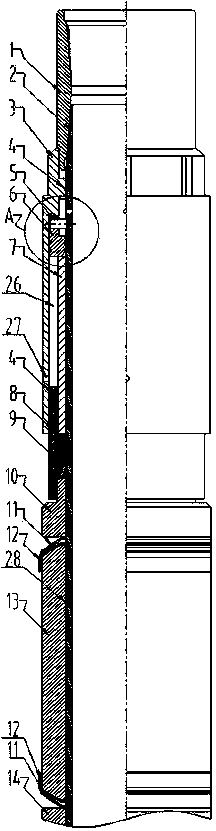
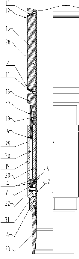
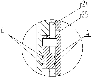
[0028] Such as Figure 1 to Figure 8 As shown, a double-cylinder compression packer includes a center pipe 2, and the upper joint 1, the upper liquid cylinder 3, the upper actuator 6, the upper piston 7, and the upper propulsion ring are sequentially installed on the center pipe 2 from top to bottom. 8. Upper moving ring 9, upper pressure ring 10, upper rubber cylinder 13, spacer ring 14, lower rubber cylinder 15, lower pressure ring 16, lower moving ring 18, lower push ring 17, lower piston 20, lower starter 21, The lower liquid cylinder 19 and the lower joint 23, the upper joint 1 is threadedly connected with the top of the central pipe 2, the upper end of the upper liquid cylinder 3 is threaded with the upper joint 1, and the upper actuator 6 and the upper piston 7 are located in the cavity of the upper liquid cylinder 3 , and the upper actuato...


PUM


Abstract

The invention discloses a double-cylinder compression packer. The double-cylinder compression packer comprises a center pipe. The center pipe is sequentially sleeved with an upper connector, an upper hydraulic cylinder, an upper starter, an upper piston, an upper impelling ring, an upper moving ring, an upper pressing ring, an upper rubber barrel, a spacer ring, a lower rubber barrel, a lower pressing ring, a lower moving ring, a lower impelling ring, a lower piston, a lower starter, a lower hydraulic cylinder and a lower connector from top to bottom. Instant impact force in the setting process of the compression packer is buffered by arranging end portion copper rings and elastic steel rings at the two ends of the upper rubber barrel and the two ends of the lower rubber barrel to prevent parts of the compression packer from being damaged by the instant impact force so that sealing pressure of the upper rubber barrel and the lower rubber barrel on a casing pipe is more even, and the service life of the compression packer is prolonged. Because a saw-tooth-shaped structure is arranged on the center pipe, the upper rubber barrel and the lower rubber barrel can be effectively prevented from wriggling in the working process. Rubber barrel frameworks are arranged on the upper rubber barrel and the lower rubber barrel in a sulfuration mode and are provided with saw-tooth-shaped structures, so that the upper rubber barrel and the lower rubber barrel are prevented from being damaged in the setting and sealing processes of the compression packer, and the elastic restoring force of the upper rubber barrel and the elastic restoring force of the lower rubber barrel are increased in the release process of the compression packer.

Description

technical field [0001] The invention relates to a packer, in particular to a double-cylinder compression packer for oil and gas development. Background technique [0002] With the increasing number of deep wells, extended-reach horizontal wells and multilateral wells, the requirements for downhole tools including packers are getting higher and higher. The currently used hydraulic packer has a long rubber tube, and after the packer is set, the shoulder of the rubber tube protrudes seriously, causing the shoulder of the rubber tube to rupture due to stress concentration, so the sealing pressure of the rubber tube is low and the service life is not long , the packing effect of the packer is not good. [0003] After the packer is set, due to the complicated stress on the packer, it is easy to cause the rubber tube of the packer to wriggle and cause the packer to lose its sealing effect. Contents of the invention [0004] The purpose of the present invention is to overcome th...

Claims


Application Information

Patent Timeline
Patent Type & Authority Applications(China)
IPC IPC(8): E21B33/126E21B33/128
Inventor 李斌杨春雷蒋宇鸿沈桓宇刘婷
Owner 齐齐哈尔亚盛机械制造有限公司
Why Eureka
Try Eureka