Method for improving well wall stability

A technology of stability and wellbore, which is applied in the field of oil drilling, can solve problems such as the accuracy of basic parameters, inconsistent well sections, and no stability assessment, etc., so as to reduce the time of drying the wellbore, reduce the drilling cycle, and improve drilling efficiency Effect

Active Publication Date: 2014-01-22
CHINA PETROLEUM & CHEM CORP +1
View PDF4 Cites 10 Cited by
  • Summary
  • Abstract
  • Description
  • Claims
  • Application Information

AI Technical Summary

Problems solved by technology

[0010] So far, a lot of work has been done on the wellbore stability of gas drilling in China, and some prediction technologies have also been formed. However, due to the difficulty in the accuracy of the acquisition of basic parameters, it can only serve as a risk reminder at present.
On the other hand, when actually designing a well, there is often no stability assessment, and most cases are designed based on experience, so it is inevitable that the actual well section is inconsistent with the pre-designed well section

Method used


Image

  • Method for improving well wall stability

Examples


Embodiment 1

[0029] Embodiment 1 spraying device

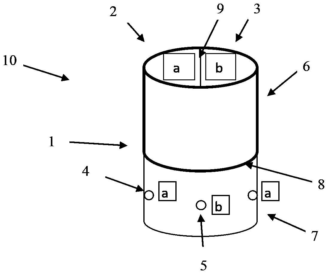
[0030] figure 1 A schematic diagram of a spraying device 10 according to the invention is shown. In this embodiment, the spraying device 10 includes a cylinder body 1, a liquid storage tank 2 and a liquid storage tank 3, and a plurality of non-existing components represented by the nozzle 4 and the nozzle 5. figure 1 The nozzles shown in all, and figure 1 A channel not shown is located in the barrel 1 for connecting the reservoir and the nozzle. Wherein, a baffle 8 is provided inside the cylinder body 1 to divide the cylinder body 1 into a first part 6 and a second part 7 . The liquid storage tank 2 and the liquid storage tank 3 are arranged inside the first part 6 of the cylinder body 1 and separated by another baffle 9 . The nozzles are arranged on the outer walls around the second part 7 of the barrel 1 . Different reservoirs correspond to different delivery pipes and nozzles.

[0031] figure 1 a and b in refer to two different spr...

Embodiment 2

[0033] Embodiment 2 increases the glue spraying method of wall stability

[0034] The spraying device in Example 1 is used for well wall support in oil drilling.

[0035] During the gas drilling process, when encountering formations that are prone to collapse or encountering formation water, the drill should be pulled out, and the air hammer or drill bit should be replaced with the spraying device as described in the embodiment. The first component and the second component of the spraying material are respectively installed in the liquid storage tank 2 and the liquid storage tank 3 . Among them, the first component is epoxy resin A glue, and the second component is epoxy resin B glue (ie curing agent). The first component and the second component alone are not adhesive, and when the two are mixed in a ratio of 1:1, the maximum adhesiveness is produced. Run the spraying device into the target well section, use the drill pipe as the gas channel, flexibly pressurize the sprayin...


PUM


Abstract

The invention provides a method for improving well wall stability. According to the method, in gas drilling, glue is sprayed on a well wall. For example, a first component of a spraying material and a second component of the spraying material are sprayed on the well wall through a spraying device. The spraying device comprises a barrel comprising a first portion and a second portion, two liquid storage tanks arranged in the first portion and containing the first component and the second component respectively, nozzles arranged on the outer peripheral wall of the second portion of the barrel and channels for connecting the liquid storage tanks and the nozzles, wherein the first component and the second component are sprayed out from different nozzles through different channels. Preferentially, the nozzles for spraying out the first component and the nozzles for spraying out the second component are arranged at intervals. According to the method, the stability of the well wall can be effectively improved, and safety and stability of oil drilling are improved. The spraying device used in the method is simple in structure and convenient to operate and enables the components of the spraying material to be fully mixed and solidified on the well wall after the components of the spraying material are sprayed out so as to form a stable blocking layer.

Description

technical field [0001] The invention relates to the field of petroleum drilling, in particular to a method for increasing the stability of well walls. Background technique [0002] The gas drilling process uses an air compressor to initially pressurize the gas, then drives it into the well after being pressurized by a booster, and finally completes the task of carrying cuttings. Gas drilling is different from drilling fluid drilling. The former is a special drilling method that directly uses gas as a circulating medium to cool the drill bit and carry cuttings to meet the needs of drilling engineering. [0003] On the basis of various emergency plans and operating procedures, the gas drilling process mainly adopts the following technical measures: A. Before gas drilling, the cement plug should be drilled with drilling fluid, and then the drilling fluid in the wellbore should be lifted out with gas, blown Dry the wellbore, continue to use the roller cone bit to drill about 5-...

Claims


Application Information

Patent Timeline
Patent Type & Authority Applications(China)
IPC IPC(8): E21B33/13
Inventor 赵金海闫冰肖莉刘建立
Owner CHINA PETROLEUM & CHEM CORP
Why Eureka
Try Eureka