
Concrete pumping device and pumping oil cylinder

A technology for concrete pumps and oil cylinders, which is used in mechanical equipment, fluid pressure actuation devices, fluid pressure actuation system components, etc. The movement cannot be carried out alone, so as to avoid additional wear, improve the lubrication effect, and prevent eccentric wear.

Active Publication Date: 2014-01-22
娄底市中兴液压件有限公司
View PDF7 Cites 8 Cited by
  • Summary
  • Abstract
  • Description
  • Claims
  • Application Information

AI Technical Summary

Problems solved by technology

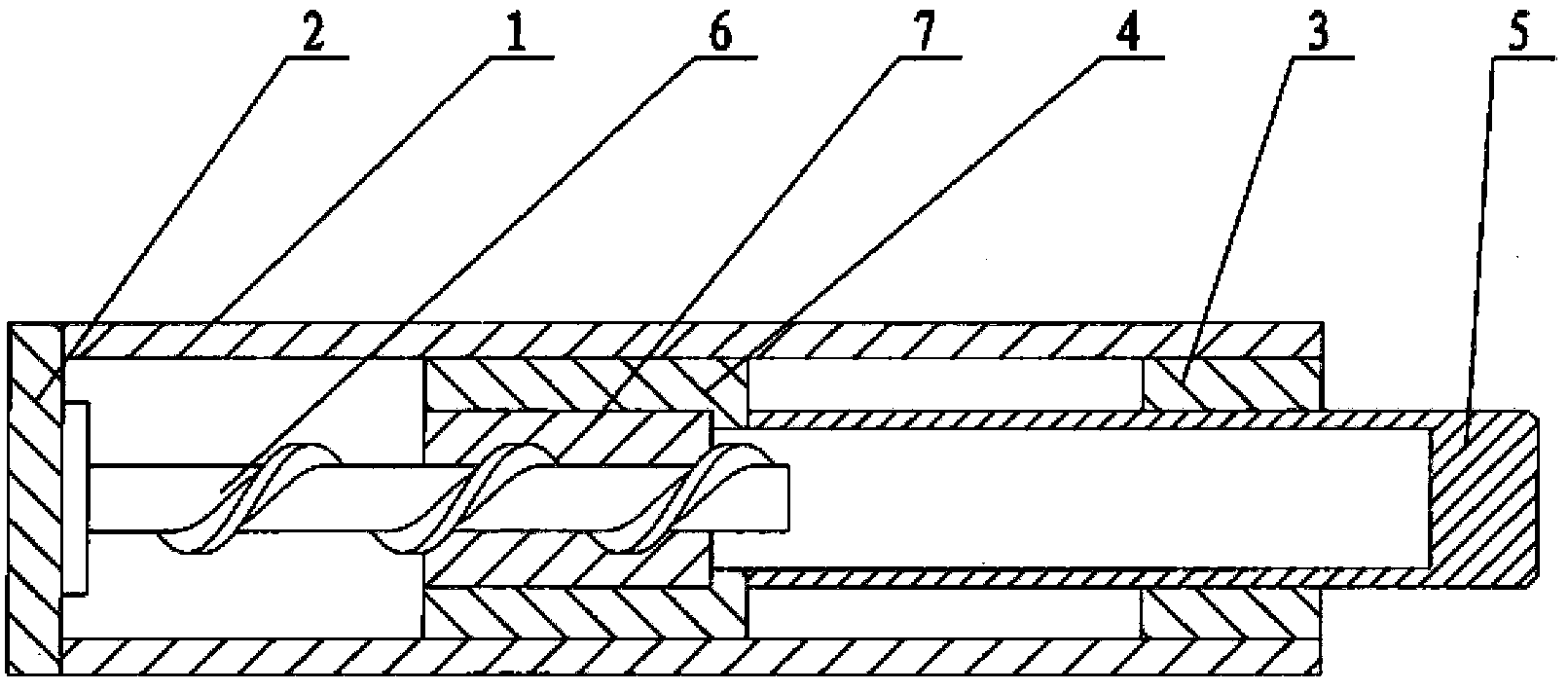
[0005] 1) The linear and rotary motions of the piston rod must be carried out simultaneously, and the two motions cannot be carried out independently. The concrete piston must also rotate when it is working, which will increase the wear of the vulnerable parts such as the concrete piston and reduce the service life;
[0006] 2) Because the piston rod cannot rotate independently, when installing and disassembling the concrete piston, it is still necessary to manually operate the piston rod, which is laborious and time-consuming

Method used


Image

  • Concrete pumping device and pumping oil cylinder
  • Concrete pumping device and pumping oil cylinder
  • Concrete pumping device and pumping oil cylinder

Examples


Embodiment Construction

[0046] It should be noted that, in the case of no conflict, the embodiments of the present invention and the features in the embodiments can be combined with each other. The present invention will be described in detail below with reference to the accompanying drawings and examples.

[0047] First of all, it needs to be explained that the orientation terms such as front and rear involved in the present invention refer to the direction of movement of the piston and piston rod of the pumping cylinder, specifically the direction in which the piston rod of the pumping cylinder pushes the concrete piston forward. , the reverse is the rear, and the related front, front, rear, and rear are all based on this.

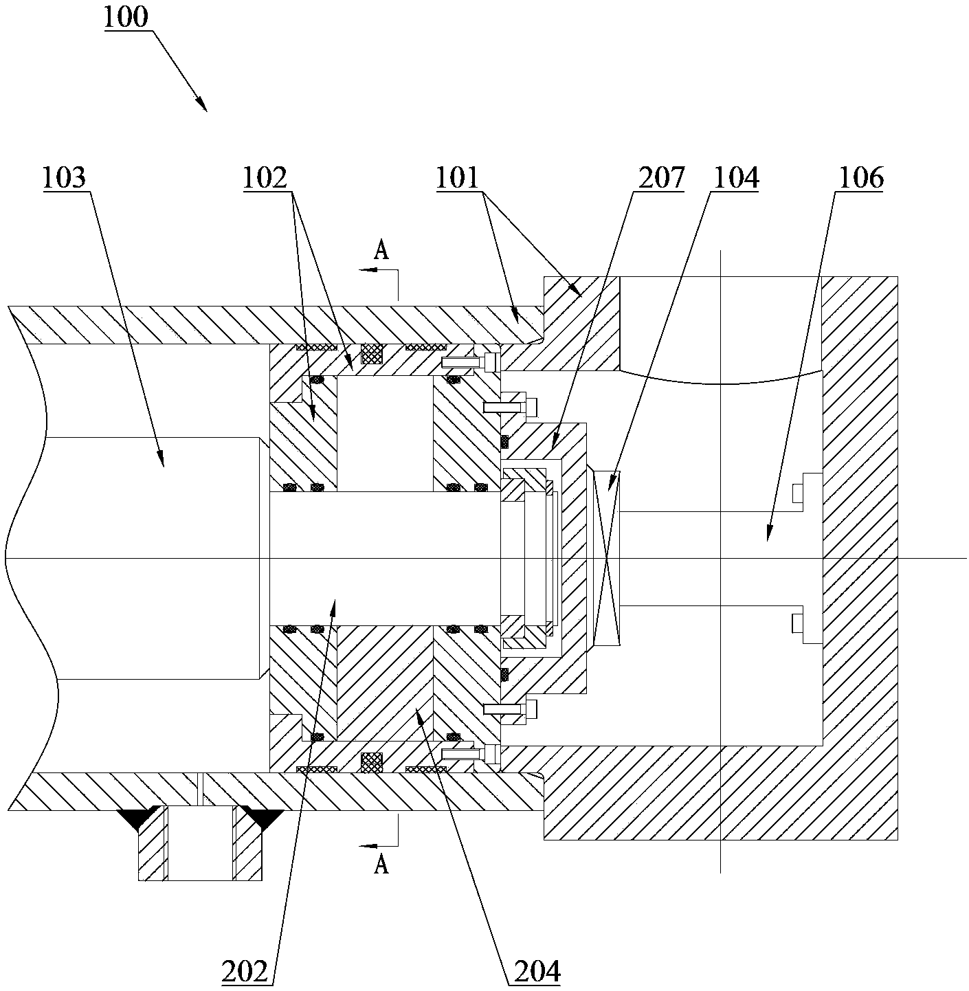
[0048]The basic design idea of ​​the present invention is to provide a new type of pumping oil cylinder for the existing problem of the movement mode of the main oil cylinder piston rod in the existing pumping oil cylinder. The pumping oil cylinder has an independent driving de...


PUM


Abstract

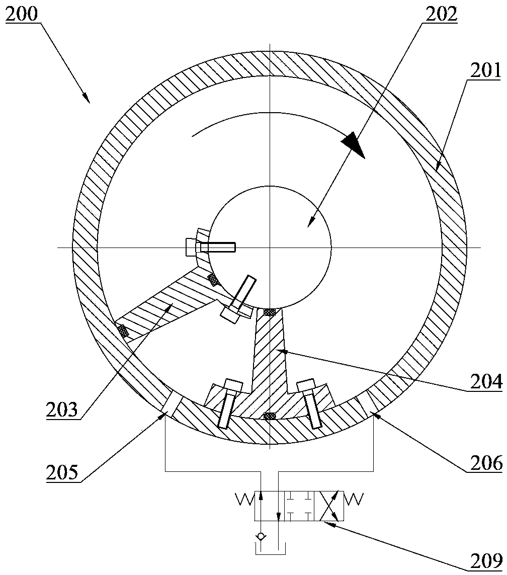
The invention discloses a concrete pumping device and a pumping oil cylinder. The pumping oil cylinder can be used in the concrete pumping device to drive a concrete piston. The pumping oil cylinder comprises a main oil cylinder body and a rotating oil cylinder body. The main oil cylinder body comprises a first cylinder barrel, a piston and a piston rod. The rotating oil cylinder body comprises a second cylinder barrel, a rotating shaft, a first blade and a first partition plate, wherein the rotating shaft is arranged on the second cylinder barrel, the axis of the rotating shaft is overlapped with the axis of the second cylinder barrel, one end of the first blade is fixedly connected with the rotating shaft, the other end of the first blade is connected with the second cylinder barrel in a sealed mode, one end of the first partition plate is fixedly connected with the second cylinder barrel, the other end of the first partition plate is connected with the rotating shaft in a sealed mode, and a first oil opening and a second oil opening are formed in the second cylinder barrel and are formed in the two sides of the first partition plate respectively. Part of parts of the rotating oil cylinder body are selectively connected with part of parts of the main oil cylinder body, and therefore the rotating shaft of the rotating oil cylinder body can selectively drive the piston rod of the main oil cylinder body. The piston rod in the pumping oil cylinder can conduct independent linear reciprocation and rotation.

Description

technical field [0001] The invention relates to the field of concrete pumping, in particular to a concrete pumping equipment and a pumping oil cylinder. Background technique [0002] The pumping mechanism in concrete products mainly includes a main oil cylinder, a concrete piston and a conveying cylinder. The main oil cylinder drives the concrete piston to reciprocate in the conveying cylinder to convey concrete materials. At present, the main oil cylinder of the pumping mechanism usually adopts a single-rod piston rod, and the piston rod can only do linear reciprocating motion. The single linear reciprocating motion inevitably causes partial wear of the concrete piston in the conveying cylinder, which leads to early scrapping of the concrete piston and increases the cost. [0003] In the prior art, some patent documents disclose a linear and rotary compound motion oil cylinder, the basic structure of which is as follows: figure 1 Shown: a screw rod 6 is fixed on the cylin...

Claims


Application Information

Patent Timeline
IPC IPC(8): F15B15/08F15B21/04
Inventor 柳桂锋高杨周昱
Owner 娄底市中兴液压件有限公司
Learn More