Saggar material mixing device

A technology of leveling device and sagger, which is applied in the field of electronic kiln auxiliary facilities, can solve the problems of low efficiency, high labor intensity of workers, and no manual shaking, so as to reduce the working intensity, excellent shaking effect, and guarantee The effect of firing quality

Active Publication Date: 2014-01-22
SUZHOU HUIKE EQUIP CO LTD
View PDF6 Cites 13 Cited by
  • Summary
  • Abstract
  • Description
  • Claims
  • Application Information

AI Technical Summary

Problems solved by technology

Because after the sagger automatic weighing and feeding device feeds the sagger, the electronic powder material in the sagger has a pagoda-shaped phenomenon. If it is not leveled, the firing of the electronic powder material in the sagger will degree of consistency is affected
[0004] In the prior art, workers usually manually shake the electronic powder material in the sagger after the automatic weighing and feeding device has completed the feeding. The disadvantage of manual shaking is that the labor intensity of the workers is high and the efficiency is low. and shaking effect is difficult to guarantee, etc.
[0005] The applicant has searched the literature, but in the patents and non-patent literature disclosed so far, there is no technical inspiration that can eliminate the shortcomings of manual shaking. For this reason, the applicant has made a positive and beneficial design, and finally The technical scheme that will be introduced below has been formed, and repeated simulation tests have been done in the applicant's laboratory under the confidentiality measures, and the results prove that it is practicable

Method used


Image

  • Saggar material mixing device
  • Saggar material mixing device

Examples


Embodiment Construction

[0020] In order to enable examiners of the Patent Office, especially the public, to more clearly understand the technical essence and beneficial effects of the present invention, the applicant will describe in detail in the form of examples below, but the description of the examples is not intended to describe the solution of the present invention. As a limitation, any equivalent transformations made according to the concept of the present invention that are merely formal rather than substantive should be regarded as the technical solution scope of the present invention.

[0021] In the following description, all concepts related to directionality such as up, down, left, right, front, and back are for the state of the illustrated position being described, so they cannot be understood as the technology provided by the present invention. Specific limitations of the program.

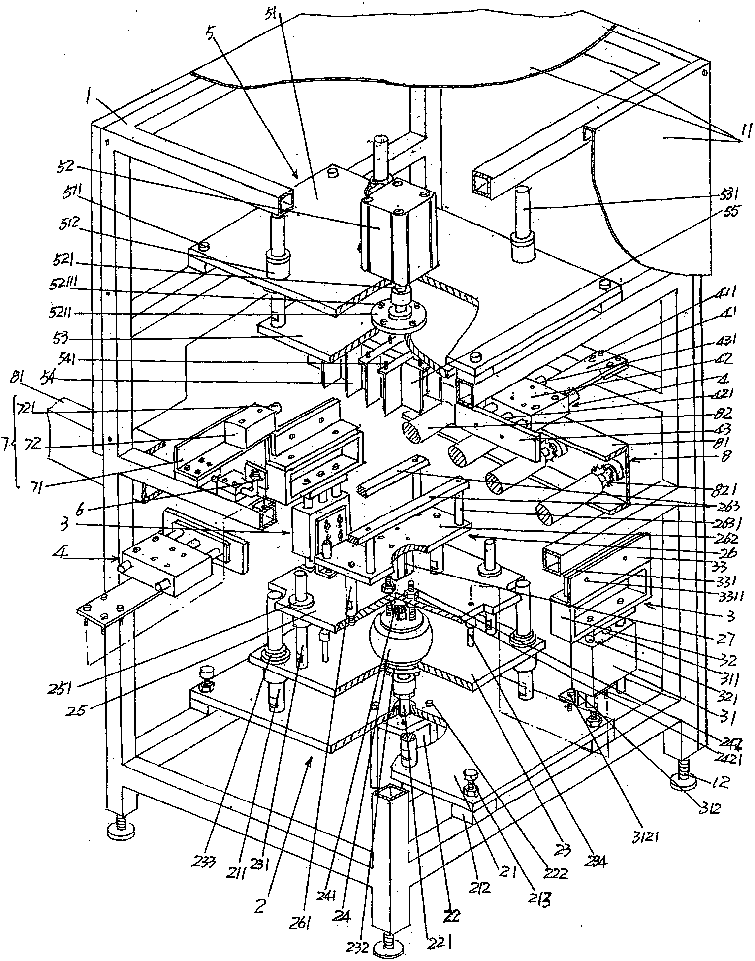
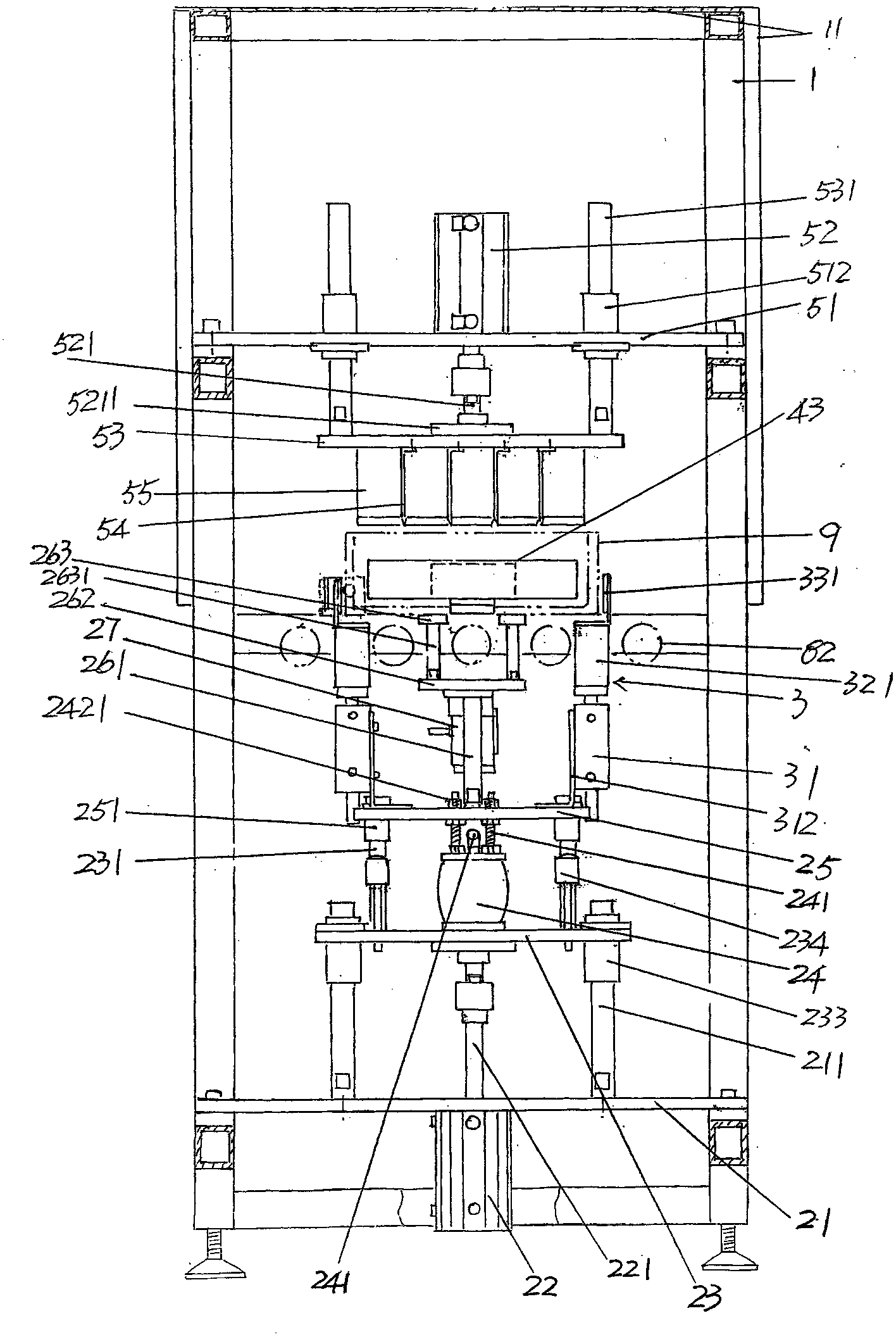
[0022] See figure 1 with figure 2 , A frame 1 belonging to the structural system of the saggar screeding de...


PUM


Abstract

The invention provides a saggar material mixing device, and belongs to the technical field of supporting facilities of an electronic kiln. The saggar material mixing device comprises a rack, a saggar jacking and vibrating mechanism, a pair of saggar material shaking and mixing mechanisms, a pair of saggar centering mechanisms, a saggar material even-distribution mechanism, a saggar position signal collector and a saggar stopping mechanism, wherein the saggar jacking and vibrating mechanism is arranged on the lower portion of the rack, the saggar material shaking and mixing mechanisms are arranged on the saggar jacking and vibrating mechanism, the saggar centering mechanisms are arranged on the two sides of the rack, the saggar material even-distribution mechanism is arranged on the upper portion of the rack and corresponds to the position above the saggar jacking and vibrating mechanism, the saggar position signal collector is also arranged on the rack and corresponds to the left side of one of the saggar centering mechanisms, the saggar stopping mechanism is also arranged on the rack and corresponds to the left side of the saggar position signal collector, and a cross-shaped positional relation is formed by the pair of saggar centering mechanisms and the pair of saggar material shaking and mixing mechanisms. The saggar material mixing device enables the work intensity to be reduced for workers beneficially, and is high in efficiency, capable of being matched with the saggar drawing speed of the electronic kiln, and excellent in shaking and mixing effect, thereby ensuring firing quality.

Description

Technical field [0001] The invention belongs to the technical field of electronic kiln auxiliary facilities, and in particular relates to a sagger screeding device, which is used for smoothing the electronic powder material loaded into the sagger from the previous process in a shaking manner, so that the electronic The material surface of the powder material is on the same level. Background technique [0002] The electronic kiln mentioned above is a special facility for firing electronic powder materials for the production of electronic components, and usually appears in the form of a production line. The so-called production line refers to the equipment around the electronic kiln for automatic transportation. The sagger automatic conveying mechanism of the sagger, which is arranged between the furnace entrance and the furnace exit of the electronic kiln, and is pivotally supported by a pair of parallel sagger conveying rollers to support beams and to rotate in a spaced state A...

Claims


Application Information

Patent Timeline
Patent Type & Authority Applications(China)
IPC IPC(8): F27D3/00
Inventor 陈龙豪惠文斌赵泉陈斌
Owner SUZHOU HUIKE EQUIP CO LTD
Why Eureka
Try Eureka