
Method for measuring and calibrating spatial position vector of point projection optical measuring head

A calibration method and spatial position technology, applied in the field of measurement, can solve the problems of low manufacturing precision of plane reference and difficulty in high-precision measurement calibration

Active Publication Date: 2014-01-22
CHINA PRECISION ENG INST FOR AIRCRAFT IND AVIC
View PDF5 Cites 11 Cited by
  • Summary
  • Abstract
  • Description
  • Claims
  • Application Information

AI Technical Summary

Problems solved by technology

[0007] Another method of measuring and calibrating the beam direction of a point-projection optical probe has been carried out in China, that is, the method of measuring and calibrating the plane angle block; this method uses two planes that form a certain angle with each other as the measurement reference; the principle of this method is to use The spatial geometric relationship between the straight line vector and the plane is used to solve the information of the beam straight line vector; the measurement reference used in this method is a plane; the manufacturing precision of the plane reference is low, and it is difficult to achieve high-precision measurement calibration

Method used


Image

  • Method for measuring and calibrating spatial position vector of point projection optical measuring head
  • Method for measuring and calibrating spatial position vector of point projection optical measuring head

Examples


Embodiment Construction

[0119] The technical scheme of the present invention will be described in further detail below in conjunction with accompanying drawing and embodiment:

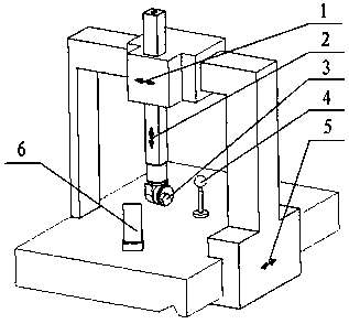
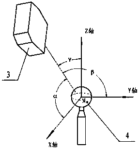
[0120] See attached Figure 1~2 As shown, the method for measuring and calibrating the spatial position vector of the point projection optical probe is characterized in that: the steps of the method for measuring and calibrating are as follows:

[0121] (1) Set a point projection optical probe 3 and a standard ball 4 on a coordinate measuring machine with a rectangular coordinate system, the measuring machine includes three linear motion axes perpendicular to each other, X axis 5, Y axis 1 and Z axis 2;

[0122] (2) By moving the X-axis 5, Y-axis 1 and Z-axis 2, use the point projection optical probe 3 to project light spots on the surface of the standard ball 4, and obtain the coordinate values ​​of the seven light spots on the coordinate measuring machine and the point projection optical probe 3 reading value, the requirem...


PUM


Abstract

The invention relates to a method for measuring and calibrating a spatial position vector of a point projection optical measuring head. The method comprises the following steps of: measuring a standard ball on a rectangular coordinate system measuring machine by utilizing the point projection optical measuring head; acquiring measuring machine coordinate information of seven light spots on the surface of the standard ball and acquiring optical measuring head reading values of the corresponding light spots; establishing a relation equation by utilizing a space geometry relation between a beam linear vector and the surface of the standard ball; and solving beam position vector information of the point projection optical measuring head. The method has the advantages of simplicity, convenience, easiness for operation and high measurement accuracy. The invention gives a measuring principle, the measuring method, measuring steps, a calculating formula and the like.

Description

technical field [0001] The invention relates to a method for measuring and calibrating the spatial position vector of a point projection optical measuring head, which belongs to the technical field of measurement. Background technique [0002] Cartesian coordinate system three-coordinate measuring machine (CMM) is a measuring machine tool with three linear motion axes (X axis, Y axis and Z axis). Coordinate changes are generated through the movement of the three axes, and are realized by touching the probe and the workpiece. Sampling measurements of part surfaces. Traditional three-coordinate measuring machines usually use contact trigger probes; contact trigger probes are zero-position signaling probes. Before measuring parts, it is only necessary to calibrate the zero position of the trigger probe in the coordinate measuring machine (the measuring machine for the probe signal position coordinate value). [0003] In the three-coordinate measuring machine of the Cartesian ...

Claims


Application Information

Patent Timeline
IPC IPC(8): G01B11/00
Inventor 房建国张谭刘勇李成玮刘飞刘京亮宋影李迪李杰毕超房亮庞长涛郑会龙
Owner CHINA PRECISION ENG INST FOR AIRCRAFT IND AVIC
Learn More