Micro-leakage detector, system with same and detection method of detector

A detection device and micro-leakage technology, applied in the direction of measuring the acceleration and deceleration rate of fluid, using liquid/vacuum degree for liquid tightness measurement, etc., can solve the problems of small leakage, safety accident, major equipment failure, etc. The effect of reducing workload, improving safety, and avoiding the expansion of accidents

Active Publication Date: 2014-01-22
CHONGQING ENDURANCE IND
View PDF5 Cites 5 Cited by
  • Summary
  • Abstract
  • Description
  • Claims
  • Application Information

AI Technical Summary

Problems solved by technology

[0003] First, when the equipment is working, it may start to leak in a small place. The traditional interlocking scheme is to stop the interlocking when the pressure drops to a certain value; but the leakage is not large at first, maybe it is Micro-leakage, if you wait until the pressure drops to a significantly lower value, the leakage may have been serious, and the equipment has changed from a small fault at the beginning to a major fault, resulting in large losses and possible safety accidents
[0004] Second, when an emergency interlock occurs, the inlet and outlet shut-off valves are closed, but because the valve itself has not been checked in place at ordinary times, there is a hidden danger of internal leakage, which may cause internal leakage, resulting in the fact that the inlet and outlet valves are not closed and the interlock effect fails
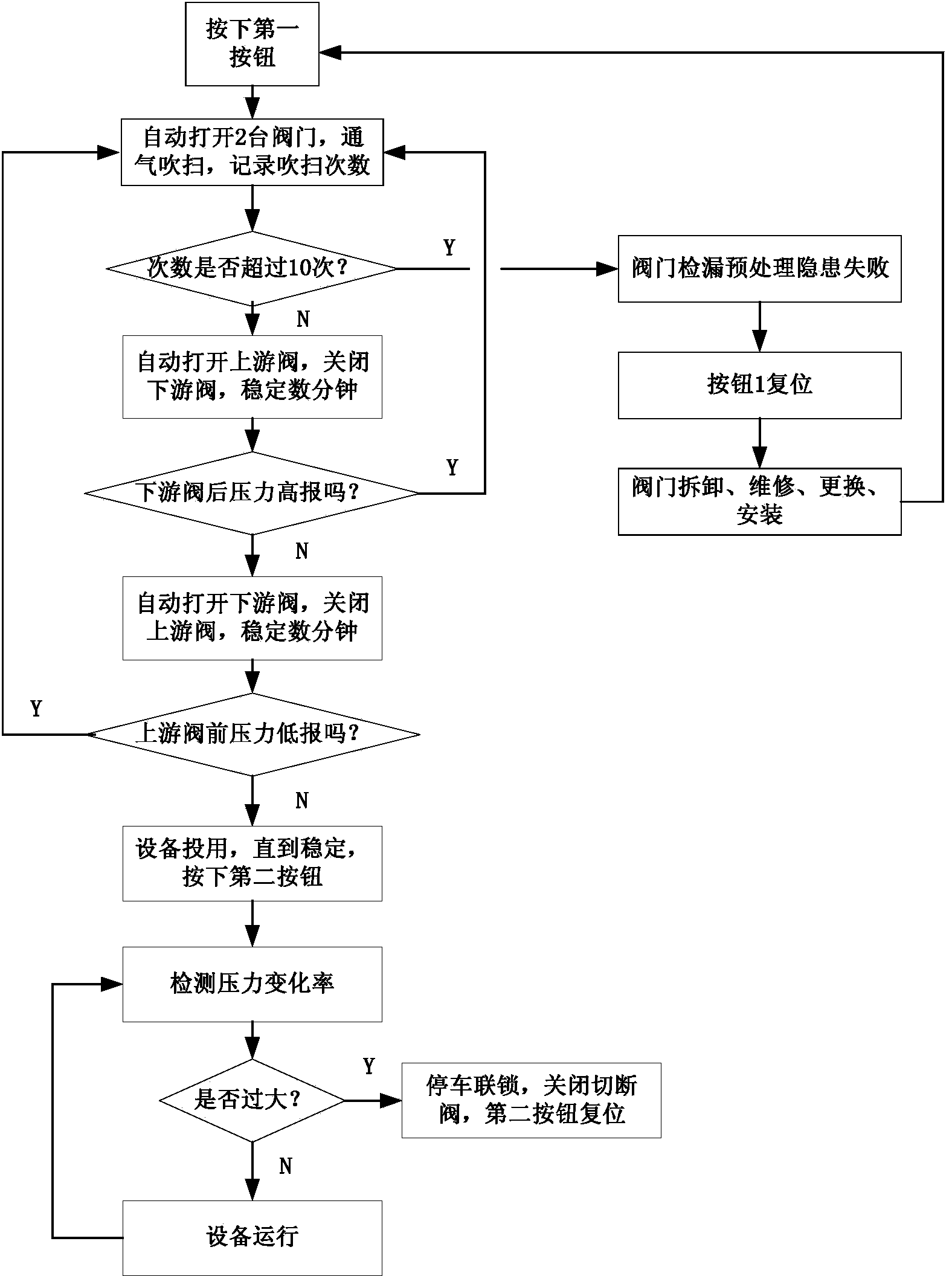
Before the equipment is put into use, the traditional valve detection method is to perform a leak detection test with ventilation. If it is unqualified, disassemble the valve, check if the internal parts of the valve are damaged, and replace the internal parts of the valve; if the inspection is not damaged, continue Install the valve, and then repeat the leak test. If it passes, it may be an accidental leak test just now.

Method used


Image

  • Micro-leakage detector, system with same and detection method of detector
  • Micro-leakage detector, system with same and detection method of detector
  • Micro-leakage detector, system with same and detection method of detector

Examples


Embodiment Construction

[0038] Embodiments of the present invention are described in detail below, examples of which are shown in the drawings, wherein the same or similar reference numerals designate the same or similar elements or elements having the same or similar functions throughout. The embodiments described below by referring to the figures are exemplary only for explaining the present invention and should not be construed as limiting the present invention.

[0039] In the description of the present invention, unless otherwise specified and limited, it should be noted that the terms "installation", "connection" and "connection" should be understood in a broad sense, for example, it can be mechanical connection or electrical connection, or two The internal communication of each element may be directly connected or indirectly connected through an intermediary. Those skilled in the art can understand the specific meanings of the above terms according to specific situations.

[0040] The inventio...


PUM


Abstract

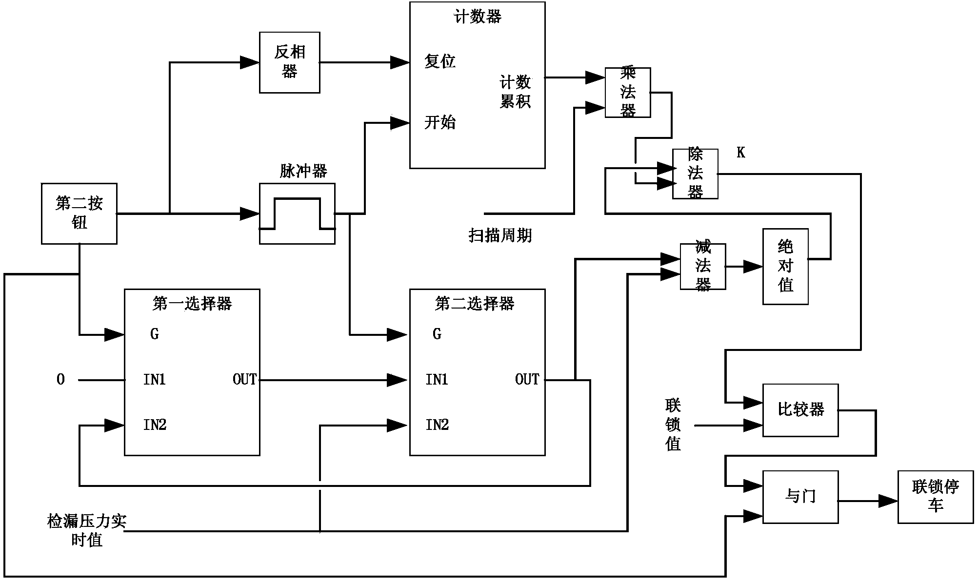
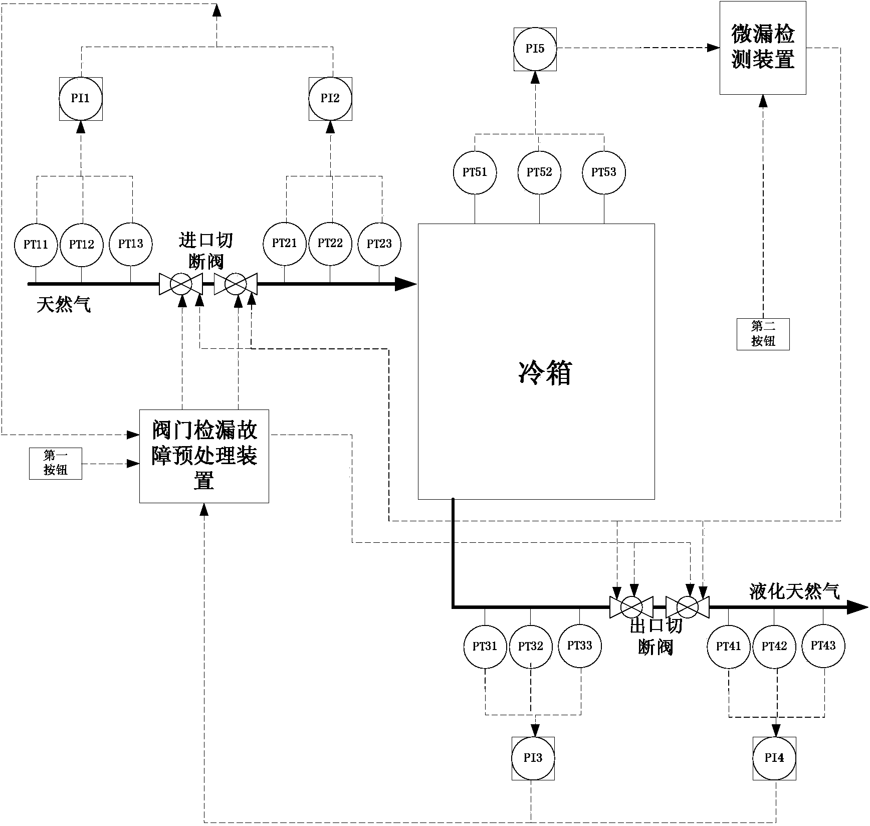
The invention provides a micro-leakage detector, a system with the same and a detection method of the detector. A micro-leakage detector and a valve leakage detecting fault preprocessing device are arranged on storage equipment; the input end of the valve leakage detecting preprocessing device is connected with the output end of a first button and is respectively connected with an air inlet air pressure sensor and an air outlet air pressure sensor; the output end of the valve leakage detecting preprocessing device is respectively connected with an inlet cutoff valve and an outlet cutoff valve; the input end of the micro-leakage detector is connected with the output end of a second button and is connected with an air pressure sensor for the storage equipment; the output end of the micro-leakage detector is respectively connected with the inlet cutoff valve and the outlet cutoff valve. According to the micro-leakage detector, the system with the same and the detection method of the detector, equipment leakage can be effectively found as soon as possible to avoid accident expanding, and non-permanent non-damaging temporary leaking hidden safety loopholes can be automatically processed in advance, so the manual workload can be reduced.

Description

technical field [0001] The invention relates to the technical field of container leak detection, in particular to a micro leak detection device, a system using the device and a detection method thereof. Background technique [0002] In the production process, various containers, reactors, towers, combustion furnaces, heat exchangers, cold boxes, compressors and other equipment are often encountered. Some of these devices are working with the possibility of flammable, explosive, toxic and harmful environmental pollution or safety accidents. Among the various causes of accidents, leakage is one of the biggest hidden dangers. [0003] First, when the equipment is working, it may start to leak in a small place. The traditional interlocking scheme is to stop the interlocking when the pressure drops to a certain value; but the leakage is not large at first, maybe it is Micro-leakage, if you wait until the pressure drops to a significantly lower value, the leakage may have become...

Claims


Application Information

Patent Timeline
Patent Type & Authority Applications(China)
IPC IPC(8): G01M3/32
Inventor 樊少冬张金桥陈昌禄魏江涛
Owner CHONGQING ENDURANCE IND
Why Eureka
Try Eureka