

Image processing device and image processing method
An image processing device and image technology, applied in image data processing, image analysis, instruments, etc., can solve the problems of huge parameters and limited scope of application.
- Summary
- Abstract
- Description
- Claims
- Application Information
AI Technical Summary
Problems solved by technology
Method used
Image

Examples
Embodiment Construction
[0024] The present invention will describe preferred embodiments for reference. The examples do not limit the scope of the present invention, but illustrate the present invention.
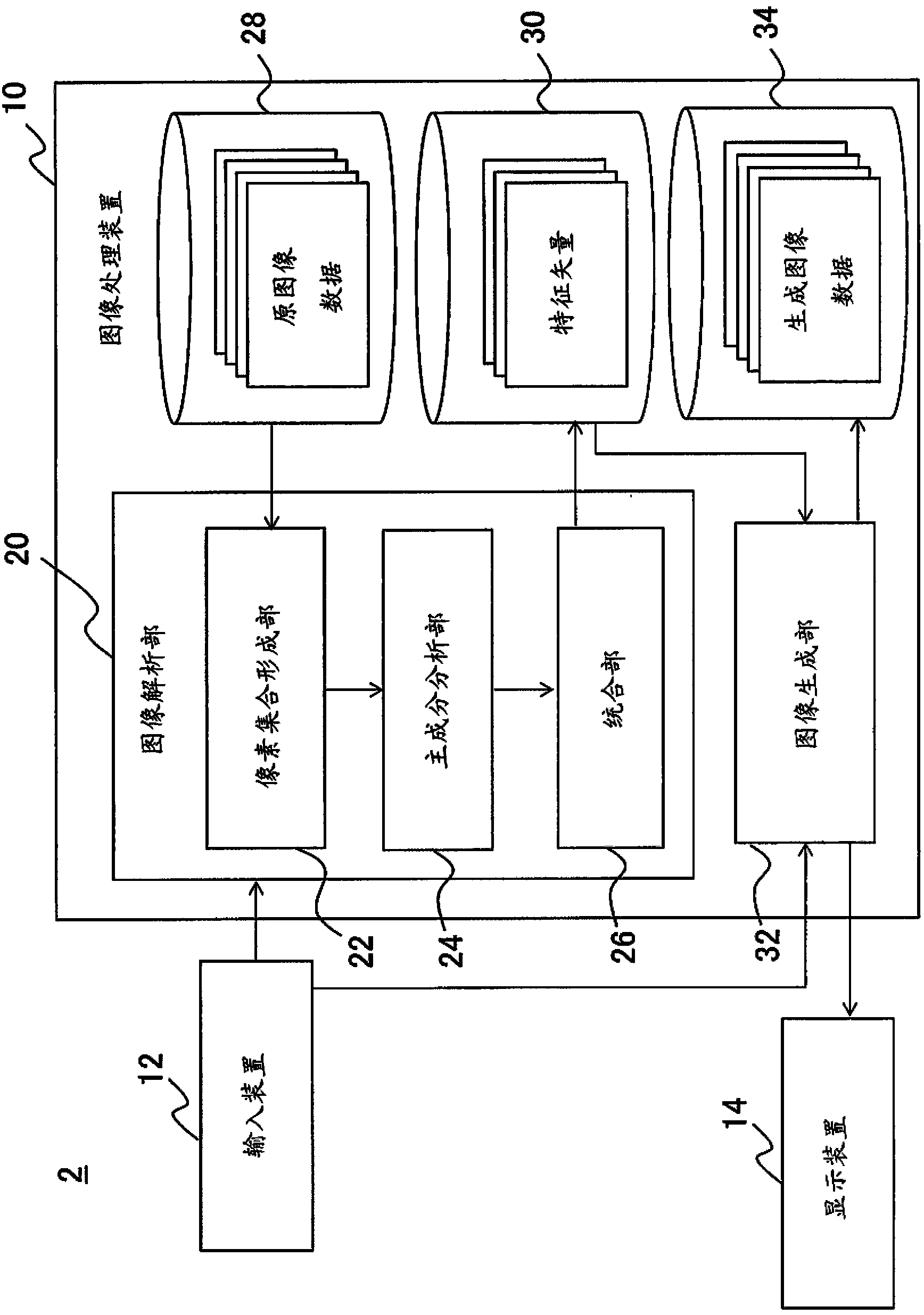
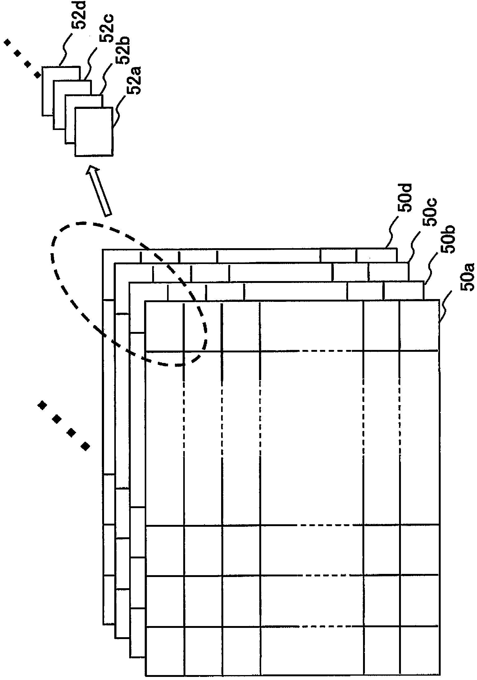
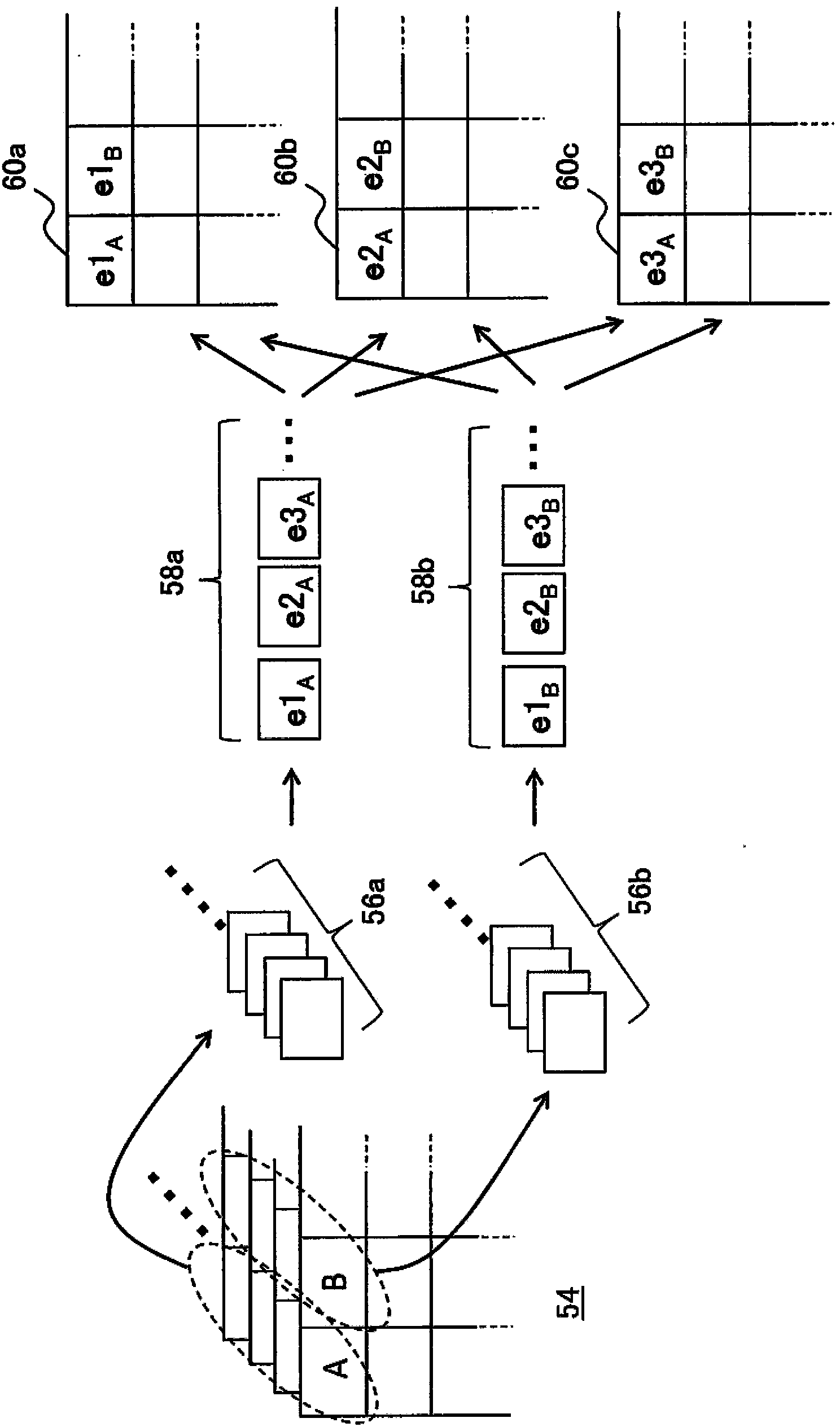
[0025] In the present embodiment, principal component analysis is performed on the entire plurality of original images so that feature vectors representing principal components can be confirmed as images. If the number of original images to be analyzed is N, then the principal component analysis is generally performed according to the following steps. First, the input data I of each original image to be analyzed is generated as follows 1 ~I N .
[0026] 〔Formula 1〕
[0027] I 1 =(p 1 (1), p 1 (2), p 1 (3), p 1 (4),...,p 1 (m)
[0028] I 2 =(p 2 (1), p 2 (2), p 2 (3), p 2 (4),...,p 2 (m)
[0029] I 3 =(p 3 (1), p 3 (2), p 3 (3), p 3 (4),...,p 3 (m)
[0030] ....
[0031] I N =(p N (1), p N (2), p N (3), p N (4),...,p N (m)
[0032] Here, p n (i) re...
PUM
 Abstract
Description
Claims
Application Information