

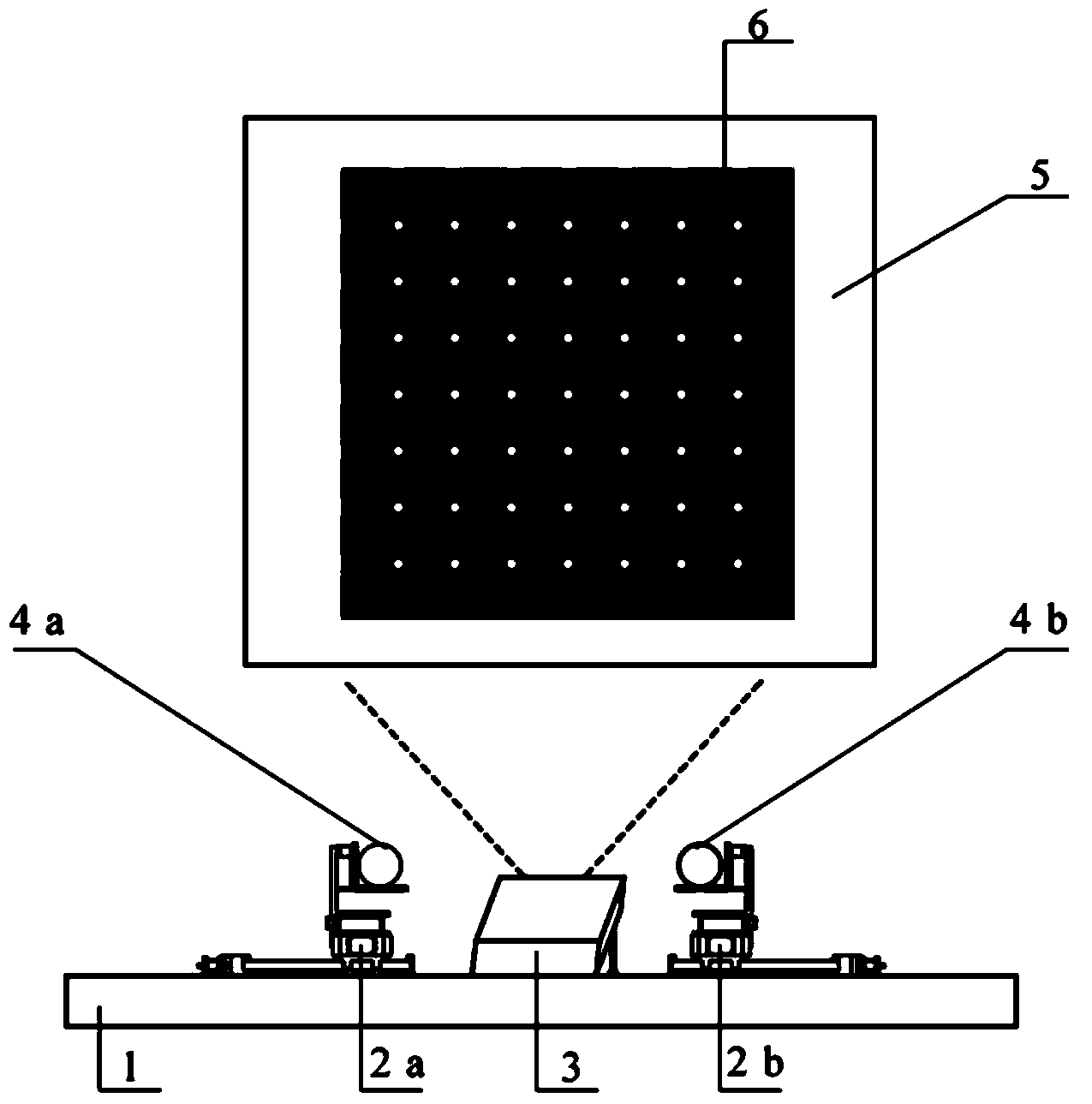
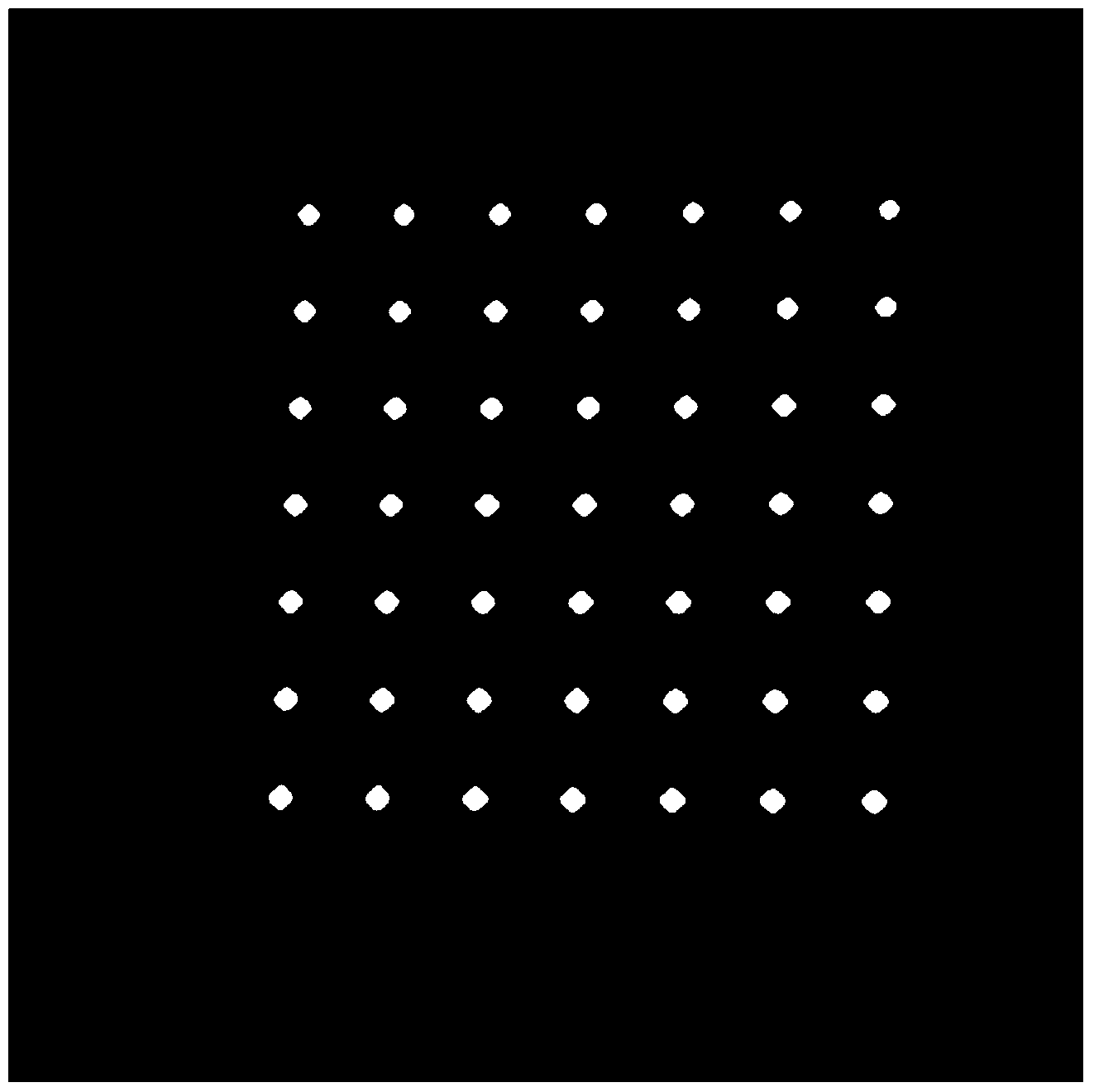
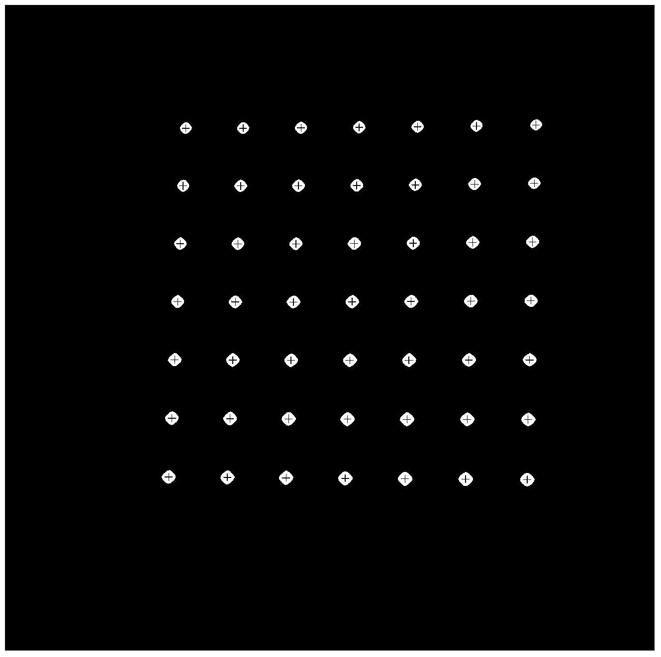
Camera calibration method based on projected Gaussian grid pattern
A camera calibration and grid pattern technology, applied in image analysis, image data processing, instruments, etc., can solve the problems of not too high, insufficient robustness, non-real-time, etc.
- Summary
- Abstract
- Description
- Claims
- Application Information
AI Technical Summary
Problems solved by technology
Method used
Image

Examples
Embodiment Construction
[0031] The specific implementation manner of the present invention will be further described in detail below in conjunction with the accompanying drawings and technical solutions.
[0032] Camera calibration usually adopts the classic pinhole imaging model, the expression of which is as follows:
[0033]
[0034] Among them, (X w ,Y w ,Z w ,1) T is the homogeneous coordinate of the spatial point in the world coordinate system, (u,v,1) T is the corresponding image pixel pixel coordinate system o 0 Homogeneous coordinates in uv, alpha x = f / dx is o 0 The scale factor on the u axis in the uv coordinate system, α y = f / dy to o 0 The scale factor on the v-axis in the uv coordinate system, f is the focal length of the camera lens, dx and dy are the horizontal and vertical physical dimensions of the pixel, (u 0 ,v 0 ) is the principal point coordinate, ρ c is the scale factor, K is the internal parameter matrix of the camera, [R|t] is the external parameter matrix of th...
PUM
 Abstract
Description
Claims
Application Information