
Aviation high-speed generator rotor structure

A high-speed generator and rotor structure technology, which is applied in the field of aviation high-speed generator rotor structure and high-speed aviation generator rotor structure, can solve the problems of increased bearing load, large friction loss on the rotor surface, and increased eccentric force, so as to reduce friction Loss issues, improved reliability, effects of reduced eccentric force

Inactive Publication Date: 2014-01-22
SHAANXI AVIATION ELECTRICAL
View PDF4 Cites 15 Cited by
  • Summary
  • Abstract
  • Description
  • Claims
  • Application Information

AI Technical Summary

Problems solved by technology

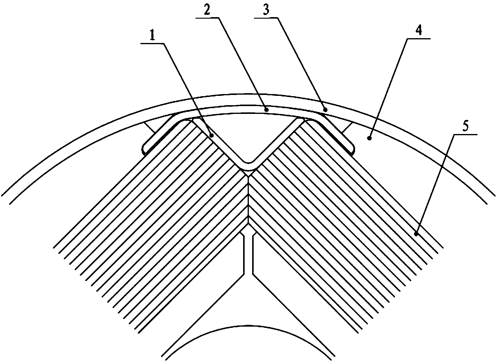
The slot wedges of this rotor structure cannot guarantee complete fit and compaction of the windings, and the winding wire package will deviate during high-speed rotation, resulting in an increase in the unbalance of the generator during high-speed rotation, resulting in an increase in eccentric force, resulting in an increase in bearing load, affecting Generator long-term reliability
In addition, since the stainless steel fin-shaped slot wedge 2 cannot be connected with the surface of the rotor pole shoe to form a complete circle, the friction loss on the rotor surface is relatively large during high-speed operation

Method used


Image

  • Aviation high-speed generator rotor structure
  • Aviation high-speed generator rotor structure
  • Aviation high-speed generator rotor structure

Examples


Embodiment Construction

[0021] Now in conjunction with embodiment, accompanying drawing, the present invention will be further described:

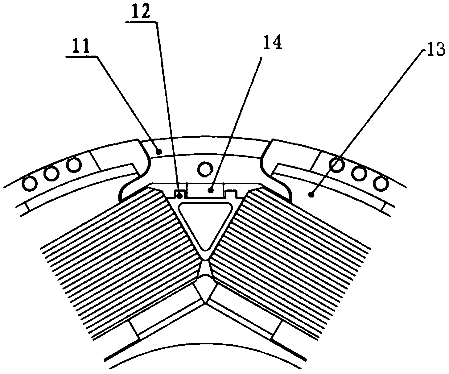
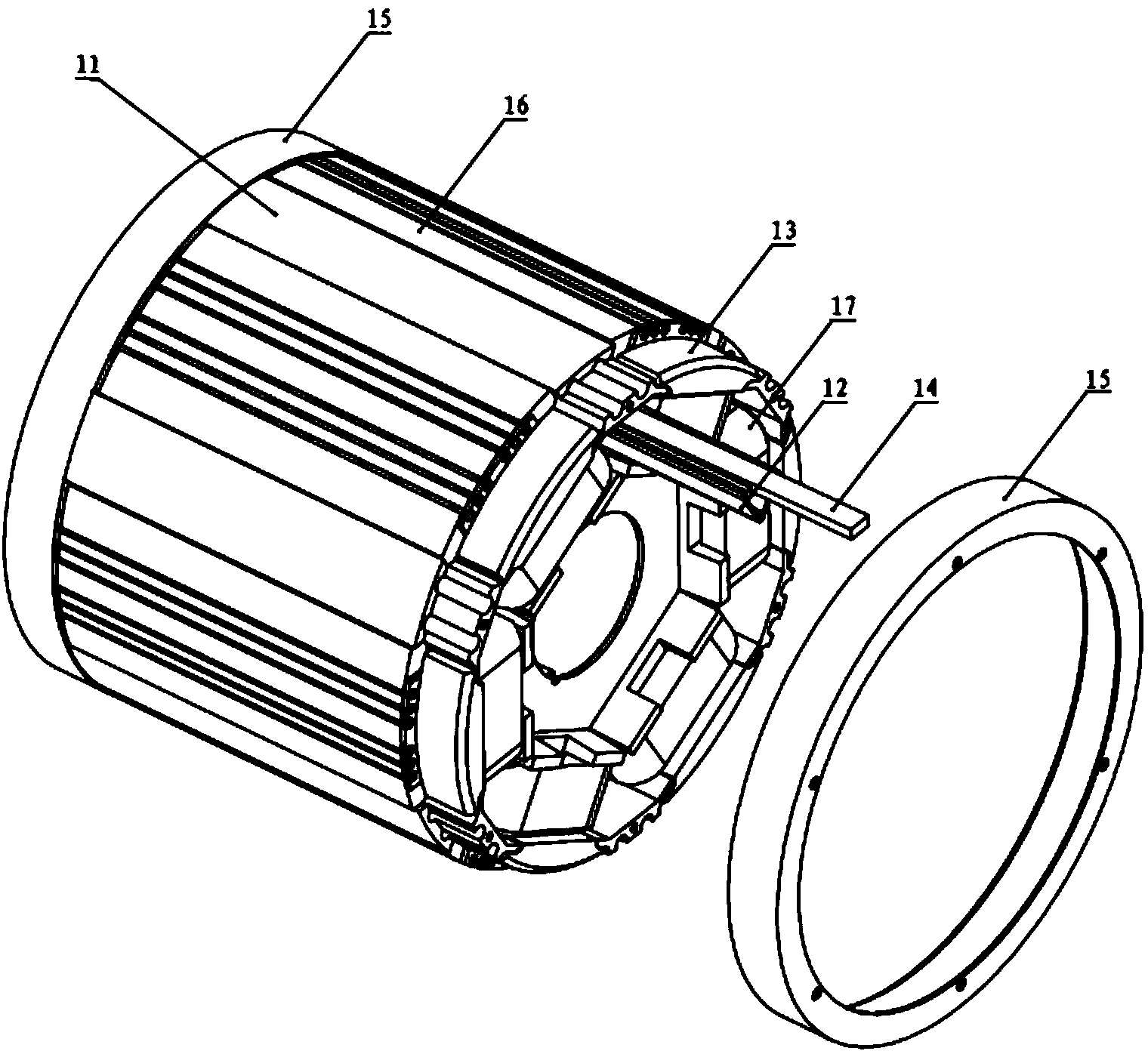
[0022] The rotor structure of the aviation high-speed generator proposed in this embodiment adopts 6 to 8 poles, and each main rotor includes two hoops 15 . Change the V-shaped slot wedge in the prior art into a triangular slot wedge 12, and set a wedge 14 on the triangular beam; make the upper surface of the wing-shaped slot wedge in the prior art flush with the outer circle of the pole core. See figure 2 .

[0023] Each pole includes a wing-shaped slot wedge 11, a triangular slot wedge 12, an insulating support 13 and two wedges 14, the insulating support 13 is assembled on both ends of the pole core 16, and after the excitation winding 5 is wound, the triangular slot wedge 12 Press the field winding from the side, the wing-shaped slot wedge 11 is inserted between the salient pole rotor pole shoe 16a and the winding, the wing-shaped slot wedge 11 presses the...


PUM


Abstract

The invention relates to an aviation high-speed generator rotor structure, which comprises a plurality of V-shaped slot wedges, a wing-shaped slot wedge, a winding, two hoop rings and a magnetic pole iron core. The aviation high-speed generator rotor structure is characterized in that the V-shaped slot wedges are changed into triangular slot wedges, a wedge block is arranged on a triangular cross beam, and the upper surface of the wing-shaped slot wedge is aligned with an excircle of the magnetic pole iron core. The aviation high-speed generator rotor structure has the advantages that the magnetic pole iron core, an excitation winding, the slot wedges and the like in a main generator rotor form a whole, the work intensity problem of products at a high rotating speed is solved, in addition, because the wing-shaped slot wedge and the surface of a rotor iron core approximately form a whole circle, the problem of surface friction loss of the high-rotating-speed rotor is reduced, and the efficiency of a generator is improved. The excitation winding on the rotor is tightly pressed by the slot wedges, so the offset of the winding during the rotation at a high rotating speed is reduced, the eccentric force reduction caused by unbalance quantity due to high-rotating-speed rotation is reduced, the load is low during the bearing rotation, and the work reliability of the generator is improved.

Description

technical field [0001] The invention belongs to aviation motor technology, in particular relates to a rotor structure of an aviation high-speed generator, and specifically relates to the application of meeting the strength requirements of the high-speed rotor of an aviation generator through the design of the rotor structure, and is suitable for the rotor structure of a high-speed aviation generator in a large passenger plane and a transport plane . Background technique [0002] Due to the particularity of the application field of aero-generator products, it is required that the aero-generator has the characteristics of light weight, high power density, and high reliability. High speed and good cooling methods are important ways for aero-generators to achieve high power-to-weight ratio. Aviation generators generally adopt a brushless three-stage winding structure, in which the main generator has a relatively large power and is a salient pole rotor. When the generator is run...

Claims


Application Information

Patent Timeline
Patent Type & Authority Applications(China)
IPC IPC(8): H02K1/22H02K3/487
CPCH02K1/24H02K3/527
Inventor 孙启月
Owner SHAANXI AVIATION ELECTRICAL
Learn More