An oil pipe installation method for an iron bracket fuel sensor, its closing structure and the mold used

An installation method and sensor technology, applied in manufacturing tools, forming tools, metal processing and other directions, can solve the problems of difficult to ensure the accuracy of pipe position, waste of materials and man-hours, product quality decline, etc., to achieve good economic and social effects, convenient Manipulation, the effect of reducing the use of materials

Active Publication Date: 2016-01-06
YANGZHOU LIANGCHENG AUTO PARTS
View PDF7 Cites 0 Cited by
  • Summary
  • Abstract
  • Description
  • Claims
  • Application Information

AI Technical Summary

Problems solved by technology

Due to this processing technology, the gap between the pipe and the punching hole needs to be sealed and fastened by argon arc welding. The welded product has a poor appearance, which not only wastes materials and man-hours, but also makes it difficult to ensure the position accuracy of the pipe. , product quality declines

Method used


Image

  • An oil pipe installation method for an iron bracket fuel sensor, its closing structure and the mold used
  • An oil pipe installation method for an iron bracket fuel sensor, its closing structure and the mold used

Examples


Embodiment Construction

[0016] The present invention will be further described below in conjunction with the accompanying drawings.

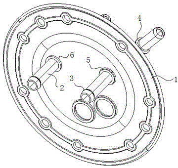
[0017] Such as figure 1 As shown, the main structure of the iron bracket fuel sensor includes a flange 1 and a fuel pipe 2. A metal plate punching hole 6 for the installation of the fuel pipe 2 is punched out on the flange 1. The diameter of the formed fuel pipe 2 is quite different from the diameter of the pipe. The diameters of the two ends of the oil pipe 2 are respectively: the small end 3 is Ф9.5+0.1 / -0.2mm, and the large end 4 is Ф10.98±0.15mm. At this time, the diameter of the punching hole 6 of the metal plate must be greater than Ф9.5, so Only the small end 3 can be loaded into the punching hole, and the conventional value is Ф9.7±0.1mm.

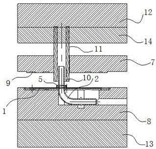
[0018] The oil pipe installation method of the iron bracket fuel sensor of the present invention is as follows: first punch out the punching hole 6 of the metal plate on the flange 1; then put the formed oil pipe 2 into the...


PUM


Abstract

The invention discloses an oil tube mounting method of an iron support fuel sensor, a nosed structure of the iron support fuel sensor and a mold used in the method. The method includes, firstly, punching a metal plate punched hole in a flange; secondly, placing a formed oil tube into the metal plate punched hole; thirdly nosing the metal plate punched hole through the nosing mold to form the oil tube nosed structure and enabling the diameter of the oil tube nosed structure to be smaller than that of the oil tube; lastly, performing welding, fastening and sealing. According to the oil tube mounting method of the iron support fuel sensor, the nosed structure of the iron support fuel sensor and the mold used in the method, by assembling the oil tube and the metal plate punched part through the nosing mold, attractive appearance as well as accurate position and dimension can be obtained, products can meet customer requirements, and the production efficiency can be effectively improved; nosing can be directly performed in a mechanical mode instead of a manual mode, so that material consumption can be reduced, production costs can be saved and good practicality can be obtained.

Description

technical field [0001] The invention belongs to the technical field of fuel oil sensors, in particular to a fuel pipe installation method for an iron bracket fuel oil sensor, a closing structure and a mold used therefor. Background technique [0002] At present, after the pipe end of the oil pipe of the iron bracket fuel sensor is formed, the diameter of the pipe end is quite different from the diameter of the pipe, and the oil pipe needs to be installed in the punched hole of the metal plate of the flange, and it needs to be tightened and sealed. Commonly used sealing and fastening methods are brazing or argon arc welding. The diameters at both ends of the oil pipe are Ф9.5+0.1 / -0.2mm and Ф10.98±0.15mm respectively. At this time, the diameter of the metal plate punching hole must be greater than Ф9 .5, the smallest head of the pipe end can be loaded into the punching hole, and the conventional value is Ф9.7±0.1mm. Due to this processing technology, the gap between the pipe...

Claims


Application Information

Patent Timeline
Patent Type & Authority Patents(China)
IPC IPC(8): B23P11/00B21D41/04B21D37/10
CPCB21D37/10B21D41/04B23P11/00
Inventor 梅峰张邵卫柯进
Owner YANGZHOU LIANGCHENG AUTO PARTS
Why Eureka
Try Eureka