Mechanical gripper

A technology of mechanical claws and drive motors, applied in the field of automation, can solve the problems of mechanical claws with many parts, complex structures, and inability to maintain the clamping state, and achieve the effects of high reliability, precise positioning, and compact structure

Inactive Publication Date: 2014-01-29
CHANGZHOU YINGSHUN ELECTRONICS
View PDF0 Cites 9 Cited by
  • Summary
  • Abstract
  • Description
  • Claims
  • Application Information

AI Technical Summary

Problems solved by technology

The general mechanical claw has many parts and complex structure, and the mechanical claw driven by the cylinder cannot maintain the clamping state after the power is removed.

Method used


Image

  • Mechanical gripper

Examples


Embodiment Construction

[0013] The following will clearly and completely describe the technical solutions in the embodiments of the present invention. Obviously, the described embodiments are only some of the embodiments of the present invention, rather than all the embodiments. Based on the embodiments of the present invention, all other embodiments obtained by persons of ordinary skill in the art without making creative efforts belong to the protection scope of the present invention.

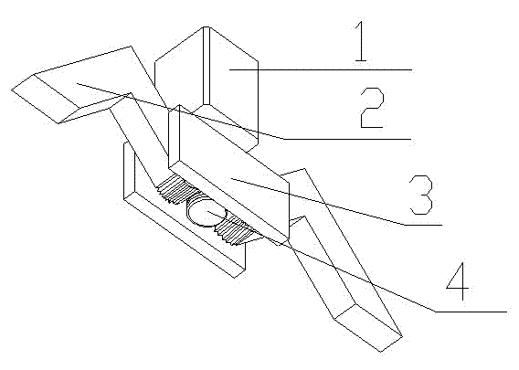
[0014] see figure 1 , the embodiment of the present invention includes:

[0015] A mechanical claw, comprising: a driving motor 1, a bracket 3, a claw 2, and a worm 4, the front end of the driving motor 1 is provided with a worm 4, the claw is installed on the bracket 3, the motor is installed in the middle of the bracket, and the claws on both sides are the same as the worm Connect to realize the drive.

[0016] The worm 4 is directly connected with the motor, and the motor provides power for the worm.

[0017] T...


PUM


Abstract

The invention discloses a mechanical gripper which comprises a drive motor, supports, jaws and a worm. The worm is arranged at the front end of the drive motor, the jaws are arranged on the supports, the motor is arranged between the supports, the jaws on the two sides are connected with the worm, and driving is achieved. Through the mode, the mechanical gripper has the advantages of being high in reliability performance, precise in locating, compact in structure, high in transposition speed, low in noise, low in price and the like, and meanwhile has wide market prospects in the field of automation.

Description

technical field [0001] The invention relates to the field of automation, in particular to a mechanical claw. Background technique [0002] Mechanical claws are commonly used devices in automation systems. They are used to carry moving objects, or to clamp and fix the required processing costs. They have the advantages of convenient use, simple structure, and good adaptability. Mechanical claws can be divided into , Double-claw, three-claw and multi-claw, can be divided into motor drive and cylinder drive according to the driving mode. General mechanical claws have many parts and complex structures, and the mechanical claws driven by the cylinder cannot maintain the clamping state after the power is removed. Contents of the invention [0003] The technical problem mainly solved by the present invention is to provide a mechanical claw, which provides clamping motion through a gear and worm mechanism, and provides power through a motor, which has high reliability, precise po...

Claims


Application Information

Patent Timeline
Patent Type & Authority Applications(China)
IPC IPC(8): B25J15/08B25B11/00
Inventor 庄棪
Owner CHANGZHOU YINGSHUN ELECTRONICS
Why Eureka
Try Eureka