
Length adjusting device for link of press machine

A technology of adjusting device and press, applied in the field of stamping and forming processing, can solve the problems of easy damage of worm gear, high scrap rate, tooth surface damage, etc., and achieve the effect of meeting processing accuracy requirements, real-time online control, and improving processing accuracy.

Inactive Publication Date: 2014-01-29
NINGBO UNIV
View PDF9 Cites 21 Cited by
  • Summary
  • Abstract
  • Description
  • Claims
  • Application Information

AI Technical Summary

Problems solved by technology

And because when the press is working, especially when the connecting rod is working for a long time, the surface temperature of the connecting rod will usually change, resulting in thermal expansion and contraction, which will cause a change in the length of the connecting rod. Therefore, the die height of the press is also real-time Corresponding micro-changes occur, although the worm gear structure is basically used to adjust the length of the connecting rod, so as to adjust the die height of the press, but after the length of the connecting rod is installed and debugged once for this structure, the length of the connecting rod It is fixed, that is, the height of the mold of the press remains unchanged, and it cannot adjust the length of the connecting rod in real time. Instead, after the press has been working for a period of time, the height of the mold is first detected, and then the length of the connecting rod is adjusted. For stamping parts that require high precision, the change of die height caused by the thermal expansion and contraction of the connecting rod during the working process of the press will lead to a high scrap rate; The pressure is high, and the stress area of ​​the worm gear teeth is small, which has a great destructive effect on the tooth surface, resulting in the worm gear being easily damaged and unable to be adjusted after a period of use

Method used


Image

  • Length adjusting device for link of press machine
  • Length adjusting device for link of press machine

Examples


Embodiment Construction

[0013] The present invention will be further described in detail below in conjunction with the accompanying drawings and embodiments.

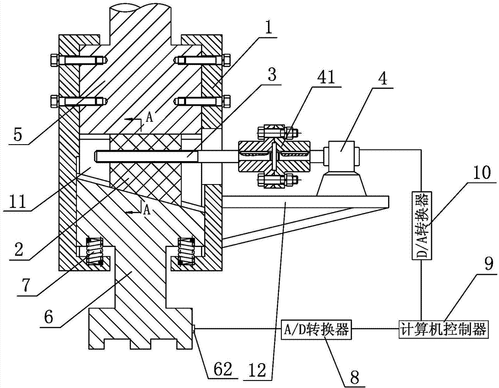
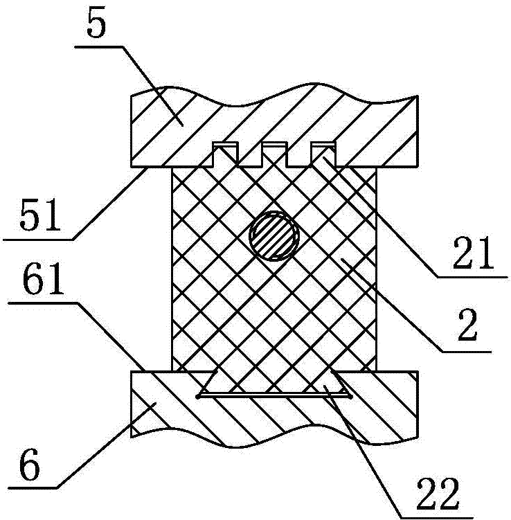
[0014] As shown in the figure, a device for adjusting the length of the connecting rod of a press includes a connecting frame 1, a wedge block 2, an adjusting screw 3, a motor 4 and a computer control system. The lower end of the connecting rod 5 in the press is fixedly connected by bolts In the connecting frame 1, the mold holder 6 for fixing the upper mold is arranged in the connecting frame 1 and slides up and down with the connecting frame 1. The lower end surface of the connecting rod 5 is a horizontal plane 51, and the upper end surface of the mold holder 6 For the oblique end surface 61 inclined downward to the right, a wedge-shaped space 11 is formed between the horizontal surface 51 of the lower end of the connecting rod 5 and the oblique end surface 61 of the upper end of the mold holder 6, and the shape of the wedge block 2 matches t...


PUM


Abstract

The invention discloses a length adjusting device for a link of a press machine. The length adjusting device is characterized by comprising a connecting rack, a wedge, an adjusting screw, a motor and a computer control system. The lower end of the link of the press machine is fixedly connected inside the connecting rack. A die holder used for fixing an upper die is disposed inside the connecting rack and in vertical sliding fit with the connecting rack. A wedged cavity forms between the lower end of the link and the upper end of the die holder. The wedge is disposed inside the wedged cavity and respectively in sliding fit with the lower end of the link and the upper end of the die holder. The wedge is screwed to the adjusting screw. The motor is fixedly mounted on the connecting rack and connected with the adjusting screw. A lock spring is vertically disposed between the die holder and the connecting rack. A displacement sensor is fixed at the bottom of the die holder. The length adjusting device has the advantages that online control can be performed in real time with the adjusting device, machining precision of a machined work piece can be improved greatly, the requirements of high precision stamping parts for machining precision can be met, and qualification rate of products is high.

Description

technical field [0001] The invention relates to stamping and forming processing of a press, in particular to a device for adjusting the length of a connecting rod of a press. Background technique [0002] When the press is stamped and formed, the workpiece is usually installed on the stamping die with a fixture, the upper die of the stamping die is mounted on the slider, and the lower die is mounted on the backing plate. Therefore, when the workpiece is fixed on the When between the upper and lower dies, punching or other stamping processes can be carried out, and the relative position of the stamping dies remains unchanged after they are installed and fixed. And because when the press is working, especially when the connecting rod is working for a long time, the surface temperature of the connecting rod will usually change, resulting in thermal expansion and contraction, which will cause a change in the length of the connecting rod. Therefore, the die height of the press i...

Claims


Application Information

Patent Timeline
Patent Type & Authority Applications(China)
IPC IPC(8): B30B15/02B30B15/26B30B15/28
Inventor 李国平姚秋水贺勇徐志明
Owner NINGBO UNIV
Learn More