
Automatic installing and detaching device of drill rod of horizontal directional drilling machine

A horizontal directional drilling rig, automatic loading and unloading technology, applied in the direction of drill pipe, drill pipe, drilling equipment, etc., can solve the problems of economic loss, personal safety, large frictional resistance, and large energy loss, and achieve the effect of avoiding useless work and saving energy consumption.

Active Publication Date: 2014-01-29
XUZHOU XUGONG FOUND CONSTR MACHINERY
View PDF5 Cites 18 Cited by
  • Summary
  • Abstract
  • Description
  • Claims
  • Application Information

AI Technical Summary

Problems solved by technology

[0003] During the construction process of the horizontal directional drilling rig, according to different conditions, it is necessary to frequently install or disassemble the drill pipe. This action is generally done manually. Repeated installation and unloading of the drill pipe may cause equipment damage due to misoperation by the operator. Or the personal injury or death of construction personnel, which will cause serious economic losses and personal safety issues
[0004] At present, although the equipment at home and abroad also uses the drill pipe loading and unloading device, the technology of adding or placing the drill pipe on the lower side of the drill pipe box is adopted, that is, the working device is required to jack up the whole box of drill pipe during work, and the horizontal movement of the drill pipe depends on reciprocating Driven by the moving shuttle arm; this technology has disadvantages such as large frictional resistance and high energy loss, and the structural parts are complex, and the mechanical wear between the structural parts is also large, which does not meet people's requirements for energy saving, consumption reduction, and environmental protection

Method used


Image

  • Automatic installing and detaching device of drill rod of horizontal directional drilling machine
  • Automatic installing and detaching device of drill rod of horizontal directional drilling machine

Examples


Embodiment Construction

[0016] The present invention will be further described below in conjunction with accompanying drawing.

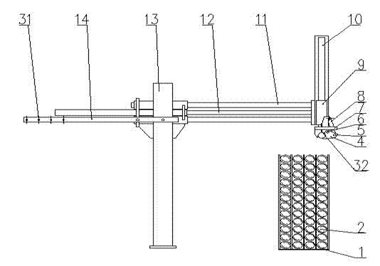
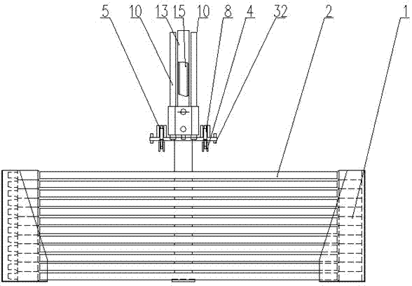
[0017] Such as figure 1 and figure 2 As shown, the automatic loading and unloading device for horizontal directional drilling rig drill pipes of the present invention includes a drill pipe box 1 and a drill pipe 2, and the drill pipe 2 is placed in the drill pipe box 1; it also includes an induction switch 3, a gripper 4, a cylinder pin 5, a pin 6. Vertical mounting base 7, grip cylinder 8, horizontal mounting base 9, vertical guide rod 10, horizontal guide rod 11, horizontal sliding cylinder 12, column 13, horizontal limit mounting plate 14 and vertical sliding cylinder 15;

[0018] The column 13 is a rectangular steel pipe, one end of which is welded with two guide sleeves parallel to each other and perpendicular to the center line of the rectangular steel pipe, and the other end is connected to the horizontal directional drilling machine through bolts;

[0019] The ho...


PUM


Abstract

The invention discloses an automatic installing and detaching device of a drill rod of a horizontal directional drilling machine. A guiding sleeve is welded to a stand column (13), and a horizontal guiding rod (11) is installed in the guiding sleeve of the stand column (13). One end of the horizontal guiding rod (11) is fixed on a horizontal installation seat (9), and a horizontal limiting installation board (14) is fixed on the stand column (13). One end of a horizontal sliding oil cylinder (12) is fixed on the horizontal installation seat (9), and the other end of the horizontal sliding oil cylinder (12) is fixed on the guiding sleeve of the stand column (13). A vertical guiding rod (10) is installed on the horizontal installation seat (9), one end of a vertical sliding oil cylinder (15) is fixed on the horizontal installation seat (9), and the other end of the vertical sliding oil cylinder (15) is fixed on a vertical installation seat (7). A second sensing switch (32) is arranged on the vertical installation seat (7), and a grasping hand oil cylinder (8) is respectively connected with the vertical installation seat (7) and a grasping hand (4). The automatic installing and detaching device can avoid idle work when the drill rod is automatically installed and detached, ensure the personal safety of operators and meanwhile reduce energy consumption.

Description

technical field [0001] The invention relates to a horizontal directional drilling machine, in particular to an automatic loading and unloading device for drilling rods of the horizontal directional drilling machine. Background technique [0002] Horizontal directional drilling rig is a construction machine for laying various underground utilities (such as pipelines, cables, etc.) without excavating the ground surface. It is widely used in water supply, electricity, telecommunications, natural gas, gas, oil and other pipelines In paving construction, it is suitable for sandy soil, clay, pebbles and other ground conditions, and it can be constructed in most non-hard rock areas in my country. [0003] During the construction process of the horizontal directional drilling rig, according to different conditions, it is necessary to frequently install or disassemble the drill pipe. This action is generally done manually. Repeated installation and unloading of the drill pipe may caus...

Claims


Application Information

Patent Timeline
Patent Type & Authority Applications(China)
IPC IPC(8): E21B19/18
Inventor 李根营张忠海吕伟祥赵国臣韩立华张力潘金良李明李凯张永华
Owner XUZHOU XUGONG FOUND CONSTR MACHINERY
Learn More