
Absorption structure of compressor

A technology for compressors and suction parts, which is applied to mechanical equipment, machines/engines, liquid displacement machinery, etc., and can solve problems such as poor startup, slow startup of the prime mover 150, and stagnation.

Active Publication Date: 2014-01-29
HOKUETSU IND
View PDF5 Cites 6 Cited by
  • Summary
  • Abstract
  • Description
  • Claims
  • Application Information

AI Technical Summary

Problems solved by technology

[0007] In the compressor constituted as above, if the compressor main body 140 is started with the suction port 143 opened, a large amount of gas is sucked into the compressor main body 140 and compressed, thereby generating a large load, and the drive for driving it The prime mover 150 is also subjected to a large load, causing a slow start-up problem of the prime mover 150, or causing a start-up failure such as stopping the prime mover 150, which is in an unstable operation state at a low rotational speed immediately after the start-up.

Method used


Image

  • Absorption structure of compressor
  • Absorption structure of compressor
  • Absorption structure of compressor

Examples


Embodiment Construction

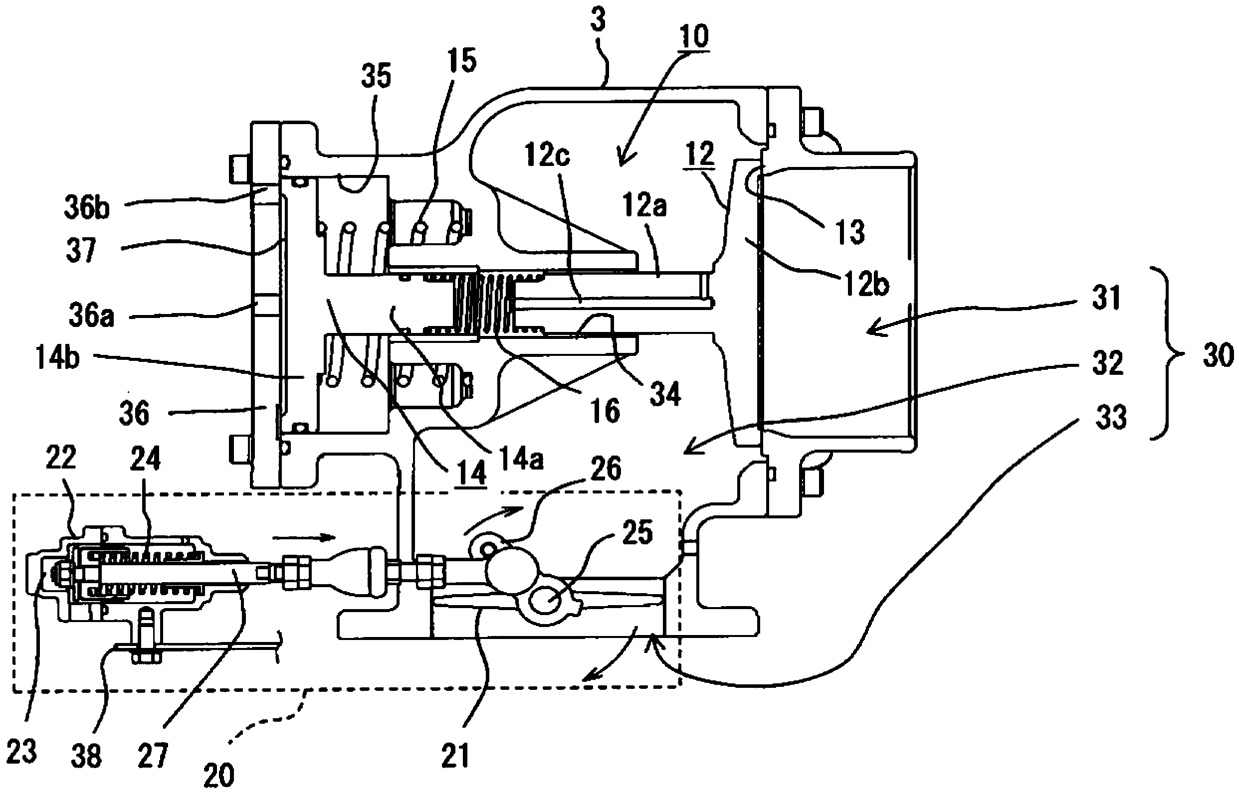
[0133] Hereinafter, the compressor of the present invention will be described with reference to the drawings.

[0134] 〔Structure of the compressor〕

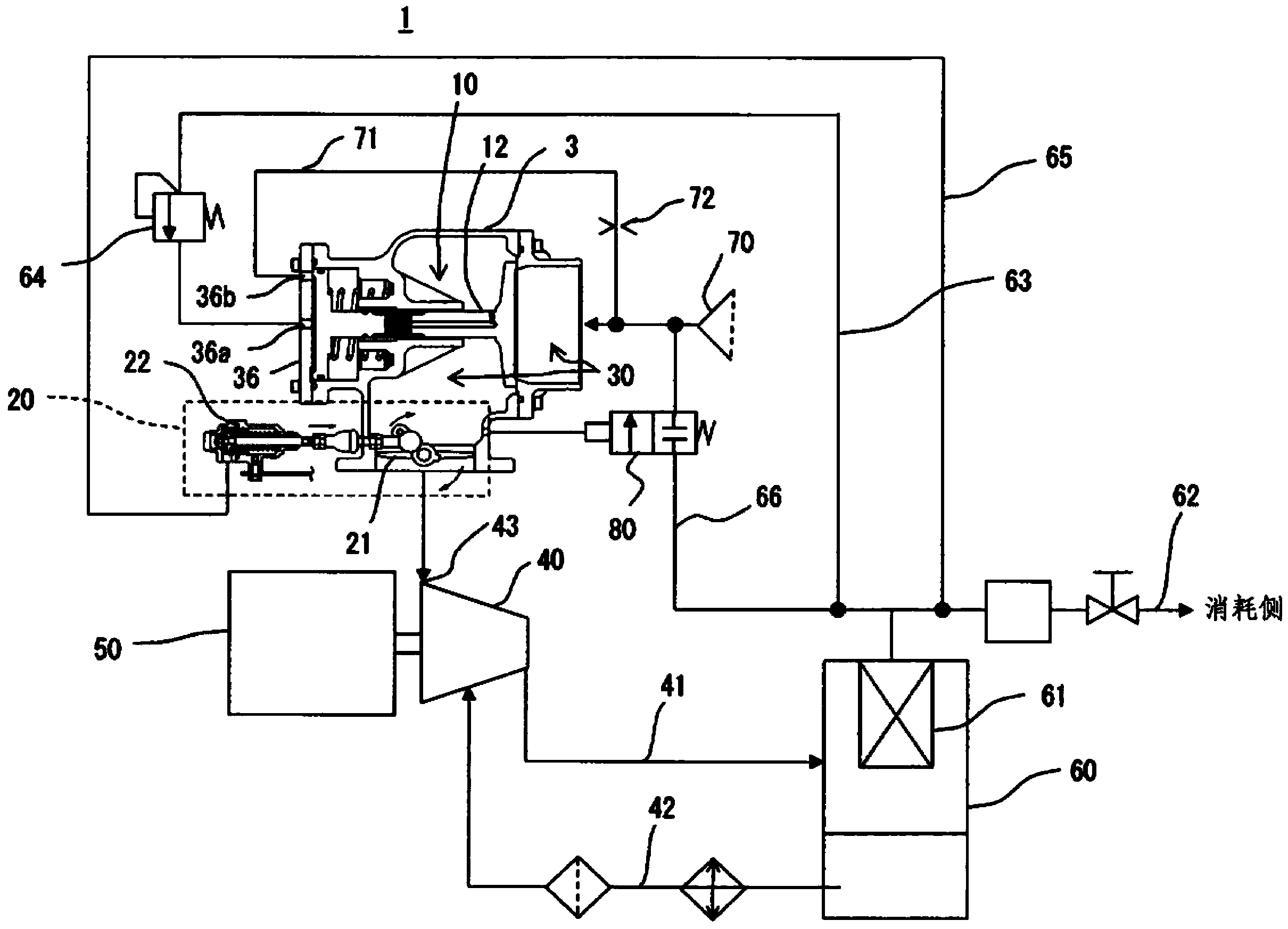
[0135] figure 1 The reference numeral 1 in is the compressor of the present invention, and the compressor 1 includes a compressor main body 40, a prime mover 50 such as an engine or an electric motor that drives the compressor main body 40, and storage from the compressor main body 40 The storage tank 60 for the ejected compressed gas. The compressed gas discharged from the compressor main body 40 is stored in the accumulator 60 , and can be supplied to the consumption side connected with an unshown air working machine or the like through a supply circuit 62 communicating with the accumulator 60 .

[0136] In this embodiment, the above-mentioned compressor body 40 uses an oil-cooled screw compressor, and a separator 61 is provided in the storage tank 60, which is used to dissipate the gas from the gas-liquid mixed fluid with ...


PUM


Abstract

The invention provides an absorption structure of compressor, when the compressor starts, the state of the absorption port of the compressor main body is kept closed, and the starting load of the prime motor is reduced. The absorption part structure of the compressor is equipped with an absorption channel which is communicated with the absorption port of a compressor main body, and a capacity control valve is equipped on the absorption channel, and the capacity control valve is equipped with a valve body, and the valve has a non-return function for permitting gas passing through from primary side to secondary side only when the valve is opened. In addition, a normal close type auxiliary switch valve is provided on the absorption channel at the primary side or the secondary side of the capacity control valve, when the pressure in a storage pot is larger or equal to initial pressure for regulated common operation, the absorption channel is opened.

Description

technical field [0001] The present invention relates to a structure of a suction part of a compressor, and more specifically, to a structure of a suction part of a compressor having a capacity control device that controls the suction of a compressor main body driven by a prime mover such as an engine or an electric motor. Gas, the pressure of the compressed gas supplied to the consumption side is controlled to be close to the specified target pressure. Background technique [0002] A capacity control device is installed in the compressor that sucks gas into the compressor main body driven by the prime mover, compresses it, and supplies the compressed gas to the consumption side connected to an air working machine, etc. The secondary side pressure controls the intake air volume of the compressor main body, and by controlling the intake air volume of the compressor main body with the capacity control device, the secondary side pressure of the compressor main body is controlled...

Claims


Application Information

Patent Timeline
Patent Type & Authority Applications(China)
IPC IPC(8): F04B49/22
Inventor 渡辺行善小熊贵泰
Owner HOKUETSU IND
Learn More