Pneumatic tube clamping valve

A pneumatic tube and pinch valve technology, applied in the direction of diaphragm valves, valve devices, valve details, etc., can solve the problems of short service life and high cost, and achieve the effect of long service life, large diameter and easy replacement

Active Publication Date: 2014-01-29
SHANGHAI NO FIVE VALVE FACTORY
View PDF5 Cites 11 Cited by
  • Summary
  • Abstract
  • Description
  • Claims
  • Application Information

AI Technical Summary

Problems solved by technology

At present, the control devices for conveying granular slurry and chemical media in low-pressure pipelines at home and abroad basically adopt the sealing method of wear-resistant metal and PTFE, which has a short service life and high cost

Method used


Image

  • Pneumatic tube clamping valve
  • Pneumatic tube clamping valve

Examples


Embodiment

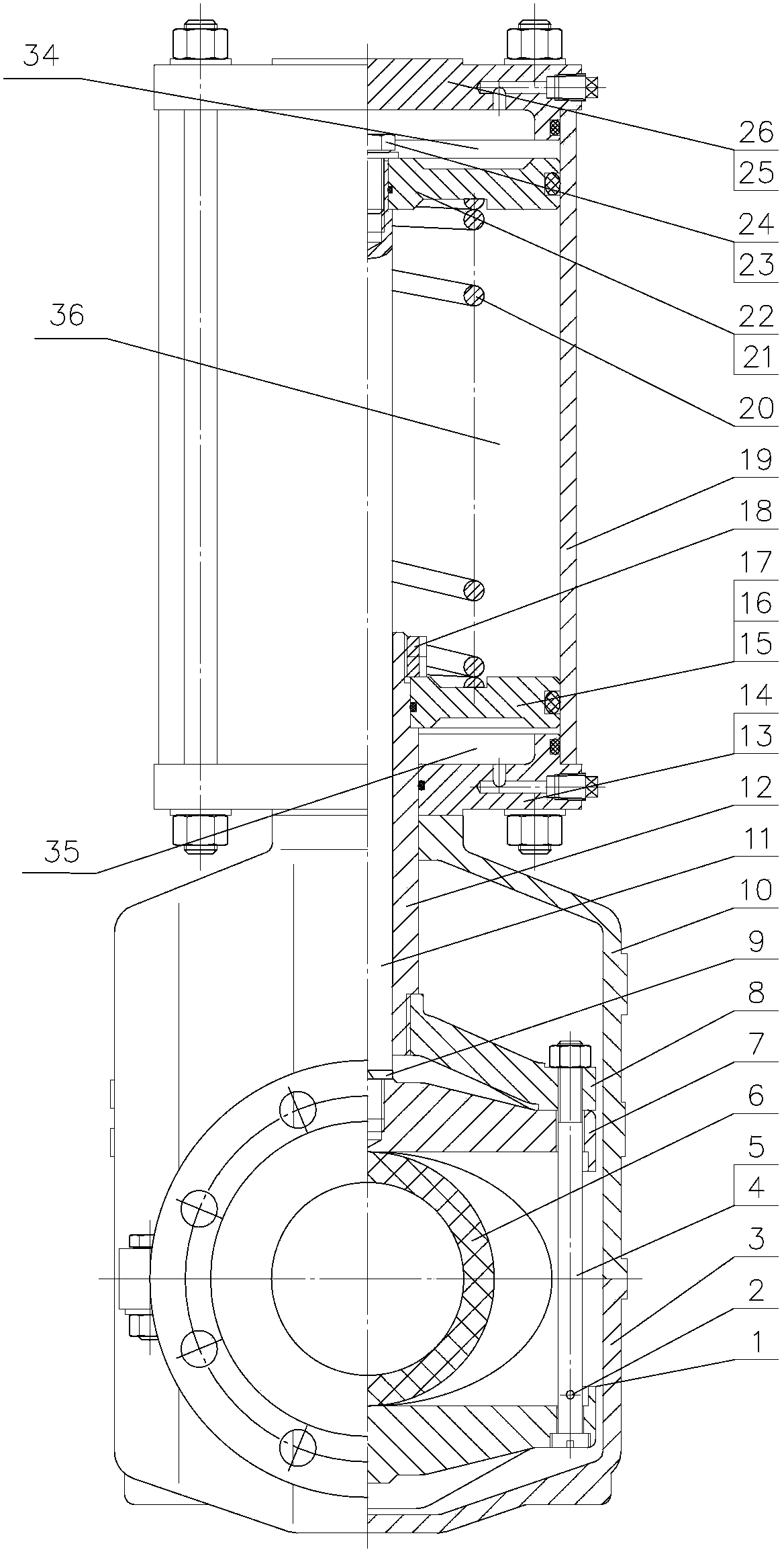
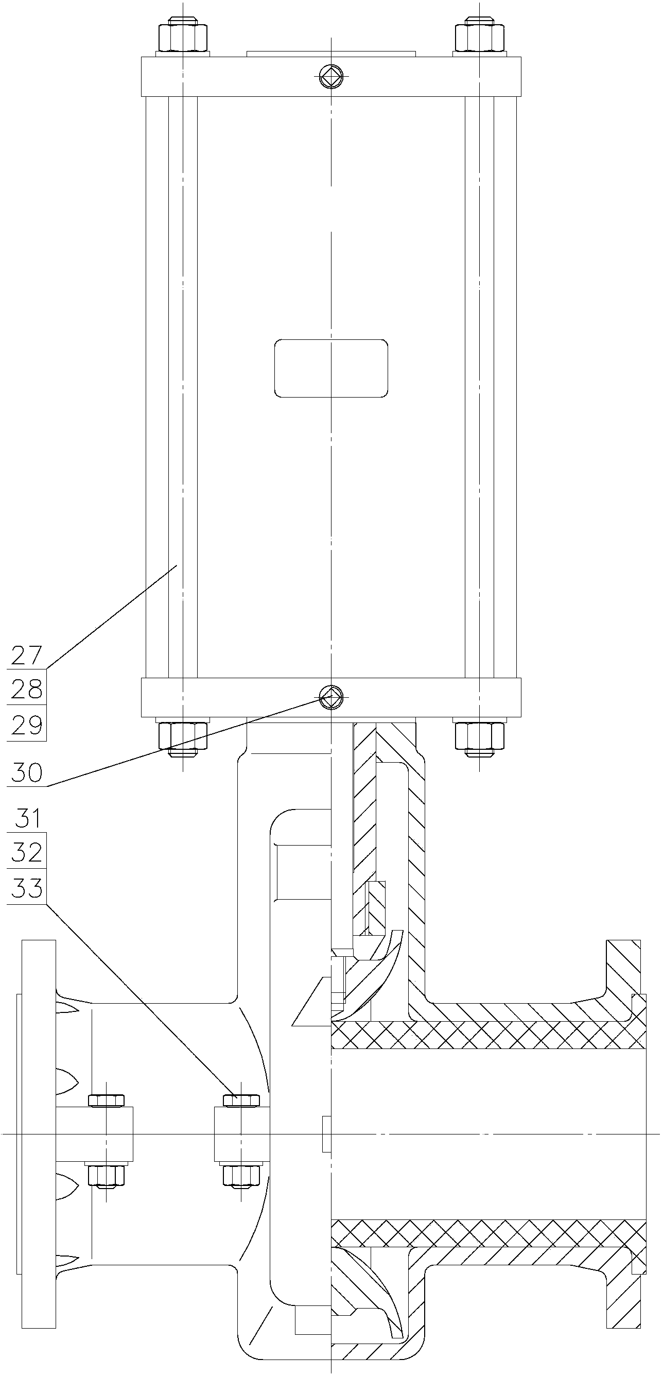
[0020] like figure 1 As shown, a pneumatic pipe pinch valve, the main components include three parts: valve body, clamping assembly and pneumatic assembly.

[0021] The valve body is composed of upper valve body 10 and lower valve body 3, which are connected by bolt II 31 and nut V33. There is also a washer IV here to enhance the locking torque of the upper and lower valve bodies. This detachable The split design makes the maintenance of the valve more convenient. The inside of the valve body is provided with a sleeve 6 as a medium flow channel.

[0022] The clamping assembly includes a small valve stem 11, a large valve stem 12, a bracket 8, a pull rod 4, an upper pressing rod 7 and a lower pressing rod 1. The small valve stem 11 is movably installed in the large valve stem 12, and is connected with the large valve stem. Rod 12 constitutes a threaded pair to facilitate the relative movement of the two. The upper pressing rod 7 is arranged at the lower end of the small valv...


PUM


Abstract

The invention relates to a pneumatic tube clamping valve which comprises a valve body, a pneumatic component and a clamping component. A sleeve used as a medium flowing channel is arranged in the valve body, the pneumatic component is arranged on the valve body, the clamping component is arranged in the valve body and is connected with the pneumatic component, and the clamping component is controlled by the pneumatic component to clamp or loosen the sleeve. Compared with the prior art, the pneumatic tube clamping valve has the advantages of being long in service life, low in cost, convenient to maintain and the like.

Description

technical field [0001] The invention relates to a valve, in particular to a pneumatic pipe pinch valve. Background technique [0002] Pneumatic pipe pinch valve is suitable for conveying ore slurry, abrasive material, fine granular dry and wet dust slurry, etc., on the pipeline of general corrosive medium with working temperature ≤ 80 ℃, and controls the opening and closing mechanism of medium flow. At present, domestic and foreign control devices for conveying granular slurry and chemical media in low-pressure pipelines have traditionally basically adopted wear-resistant metal and PTFE sealing methods. This method has a short service life and high cost. Contents of the invention [0003] The object of the present invention is to provide a pneumatic pipe pinch valve with long service life, low cost and convenient maintenance in order to overcome the above-mentioned defects in the prior art. [0004] The purpose of the present invention can be achieved through the followin...

Claims


Application Information

Patent Timeline
Patent Type & Authority Applications(China)
IPC IPC(8): F16K7/07F16K31/122F16K31/44F16K27/00
CPCF16K7/063F16K7/07F16K27/00
Inventor 苏仕平赵子慧王超
Owner SHANGHAI NO FIVE VALVE FACTORY
Why Eureka
Try Eureka