
High-precision thermocouple input module and measurement method

An input module, thermocouple technology, applied in the direction of measuring heat, measuring devices, thermometers, etc., can solve the problem that the measurement accuracy cannot be improved, and there is no measuring range.

Active Publication Date: 2014-01-29
SHANGHAI POWER EQUIP RES INST
View PDF5 Cites 0 Cited by
  • Summary
  • Abstract
  • Description
  • Claims
  • Application Information

AI Technical Summary

Problems solved by technology

[0005] On the surface, the measurement accuracy of thermocouple signals will be concentrated on the analog-to-digital converter (ADC). Generally, the analog-to-digital converter uses 12 bits, although the theoretical resolution of the analog-to-digital converter is 1 / 4096 (that is, 2 / 10,000). , but due to the reference voltage of components such as amplifiers and analog-to-digital converters and the temperature drift of components such as resistors, etc., in fact, the measurement accuracy of the entire thermocouple signal is generally between 0.1 and 0.2%. The digital converter is increased to 13 or 14, or even 15, but the overall measurement accuracy cannot be improved much
[0006] In industrial process control, this relative accuracy is not a big problem for process variables such as valve opening, pressure, flow, liquid level, voltage and current of the actuator, but for temperature signals, because it has no specific range, Under normal circumstances, the thermocouple input module is compatible with thermocouple signals of various graduation numbers, and the thermoelectric potential signal used will have enough upper limit margin, and the upper limit of the converted temperature range will reach 2000°C. At this time, the relative accuracy is converted into an absolute value. It will reach 2℃~4℃

Method used


Image

  • High-precision thermocouple input module and measurement method

Examples


Embodiment Construction

[0019] In order to make the present invention more comprehensible, preferred embodiments are described below in detail with accompanying drawings.

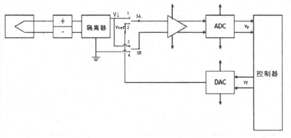
[0020] Such as figure 1 As shown, a high-precision thermocouple input module provided by the present invention includes an isolator, an amplifier, an analog-to-digital conversion unit ADC, a controller, a digital-to-analog conversion unit DAC, and an electronic switch. The isolator is connected to the thermocouple, and the amplifier The output end of the analog-to-digital conversion unit ADC, the output end of the analog-to-digital conversion unit ADC is connected to the controller, and is characterized in that the ground terminal of the isolator is connected to the grounding interface 4 at the same time as it is grounded, and the voltage output terminal of the isolator is also drawn out Two interfaces are the first voltage output interface 1 and the second voltage output interface 3. The controller outputs a feedback signal to the d...


PUM


Abstract

The invention relates to a high-precision thermocouple input module comprising an isolator, an amplifier, an analog-digital conversion unit, a controller, a digital-analog converting unit and an electronic switch. The isolator is connected with a thermocouple, the output end of the amplifier is connected with the analog-digital conversion unit, and the output end of the analog-digital conversion unit is connected to the controller. The module is characterized in that the grounding end of the isolator is grounded and outputs a grounding joint outwards; the voltage output end of the isolator outputs two joints outwards; the controller outputs feedback signals to the digital-analog converting unit according to signals acquired from the analog-digital conversion unit; and the output end of the digital-analog converting unit outputs an input joint outwards. Another technical scheme of the invention provides a high-precision thermocouple input measuring method adopting the thermocouple input module. The module has the advantages that the entire absolute accuracy of thermocouple signals is guaranteed to range from 0.1 to 0.2 DEG C, the absolute precision can achieve 0.005 to 0.01%, and actual requirements of the industrial control process can be met.

Description

Technical field [0001] The invention relates to a high-precision thermocouple input module and a measurement method, which are used to improve the measurement accuracy of small signals such as thermocouples or millivolts, and belong to the technical field of automatic control instruments. Background technique [0002] A thermocouple consists of two metal wires of different components connected at their ends to form a closed loop. One end directly used to measure the temperature of the medium is called the working end (also called the measuring end), and the other end is called the cold end (also called the compensation End), when there is a temperature difference between the working end and the cold end, there will be current passing through the loop. At this time, there will be a thermoelectromotive force (Seebeck effect) between the two ends. Choose different metal materials according to the situation. A voltage output approximately proportional to the temperature difference. ...

Claims


Application Information

Patent Timeline
Patent Type & Authority Applications(China)
IPC IPC(8): G01K7/02
Inventor 章伟杰朱武亭张文
Owner SHANGHAI POWER EQUIP RES INST
Learn More