Refrigerator

A technology for refrigerators and cold rooms, applied in the field of refrigerators, which can solve the problems of reducing the amount of frost in coolers 105, etc.

Active Publication Date: 2014-01-29
PANASONIC CORP
View PDF11 Cites 13 Cited by
  • Summary
  • Abstract
  • Description
  • Claims
  • Application Information

AI Technical Summary

Problems solved by technology

[0076] However, in the above-mentioned existing structure, for example, from the end of the full-open defrosting mode, regardless of whether the time for suspending the recirculation cooling mode is long or short, the next defrosting mode is started at the same time interval, but actually The amount of frost attached to the cooler 105 is reduced when the recirculation cooling mode is suspended for a long time
[0077] As a result, although the time of one defrosting mode is shortened, since the defrosting operation is performed when the amount of frosting is small, and the number of times of the defrosting mode per unit time is the same, there is a problem that the temperature of the storage room is raised unnecessarily.

Method used


Image

  • Refrigerator
  • Refrigerator
  • Refrigerator

Examples


no. 1 approach )

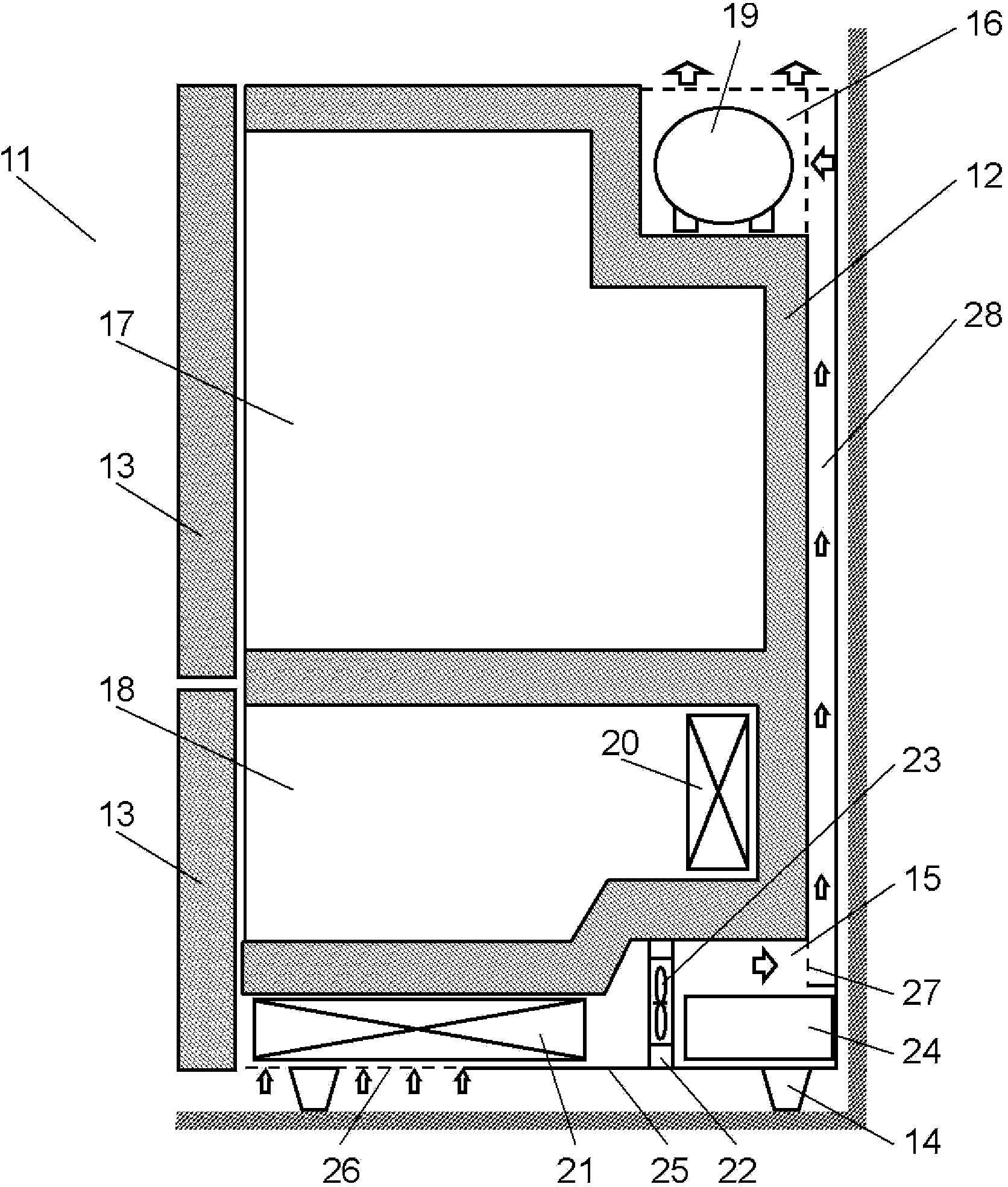
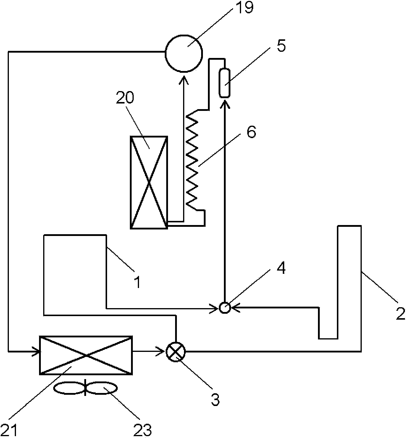
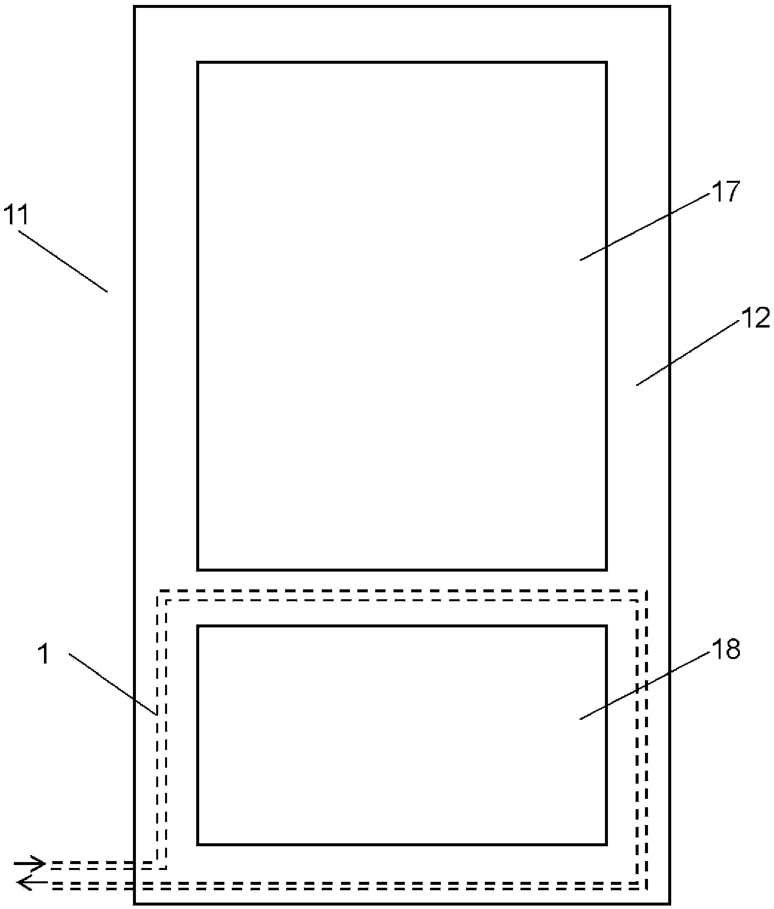
[0125] figure 1 It is a longitudinal sectional view of the refrigerator in the first embodiment of the present invention, figure 2 is a cycle configuration diagram of the refrigerator in the first embodiment of the present invention, image 3 is a schematic diagram of the front of the refrigerator in the first embodiment of the present invention, Figure 4 is a schematic diagram of the back of the refrigerator in the first embodiment of the present invention, Figure 5 It is a schematic diagram of the control pattern of the refrigerator in 1st Embodiment of this invention.

[0126] exist figure 1 Among them, the refrigerator 11 includes: a box body 12, a door 13, a foot 14 supporting the box body 12, and is formed with a lower machine room 15 arranged at the bottom of the box body 12, an upper machine room 16 arranged at the upper part of the back side of the box body 12, Refrigerating room 17 as a store room arranged at the upper part of box body 12 and freezer room 18...

no. 2 approach )

[0156] Image 6 It is a longitudinal sectional view of the refrigerator in 2nd Embodiment of this invention, Figure 7 is a cycle configuration diagram of the refrigerator in the second embodiment of the present invention, Figure 8 is a dynamic waveform diagram of the temperature sensor of the refrigerator in the second embodiment of the present invention, Figure 9 It is a flowchart which shows the control at the time of defrosting of the refrigerator in 2nd Embodiment of this invention.

[0157] exist Image 6 and Figure 7 Among them, the refrigerator 11 has: a box body 12, a door 13, a foot 14 supporting the box body 12, a lower machine room 15 arranged at the bottom of the box body 12, an upper machine room 16 arranged at the top of the box body 12, and a The refrigerating chamber 17 on the upper part of the housing 12 and the freezing chamber 18 on the lower part of the casing 12 are arranged. Also, components constituting the refrigeration cycle include a compress...

no. 3 approach )

[0193] Figure 10 It is a longitudinal sectional view of the refrigerator in the 3rd Embodiment of this invention, Figure 11 is a cycle configuration diagram of the refrigerator in the third embodiment of the present invention, Figure 12 It is a waveform diagram of the dynamics of the temperature sensor of the refrigerator in the third embodiment of the present invention.

[0194] exist Figure 10 and Figure 11 Among them, the refrigerator 11 has: a box body 12, a door 13, a leg 14 supporting the box body 12, a lower machine room 15 arranged at the lower part of the box body 12, an upper machine room 16 arranged at the upper part of the box body 12, and an upper machine room 16 arranged at the box body 12. The refrigerating chamber 17 on the upper part of the housing 12 and the freezing chamber 18 on the lower part of the casing 12 are arranged. Also, components constituting the refrigeration cycle include a compressor 19 housed in the upper machine compartment 16 , an ...


PUM


Abstract

A refrigeration cycle comprising at least a compressor (19), an evaporator (20) and a condenser is provided inside a casing. The condenser comprises a forced-air-cooling main condenser (21), a flow passage switching valve (3) connected to the downstream side of the main condenser (21), and an auxiliary condenser connected to the downstream side of the flow passage switching valve (3). The auxiliary condenser comprises a plurality of anti-condensation pipes (1, 2) connected in parallel, and refrigerant flows in parallel to the plurality of anti-condensation pipes (1, 2) when the refrigeration cycle is operated under high load conditions.

Description

technical field [0001] The present invention relates to a refrigerator having a condenser pipe (hereinafter referred to as "dew prevention pipe") for preventing dew condensation on a wall surface, which suppresses pressure loss caused by the dew prevention pipe. [0002] In addition, the present invention also relates to a refrigerator, which has dampers for blocking cold air in the freezer compartment and the refrigerator compartment, respectively, and uses one evaporator to cool the freezer compartment and the refrigerator compartment separately, thereby improving the efficiency of the refrigeration cycle. [0003] In addition, the present invention relates to a refrigerator, and in particular, to a control for suppressing an increase in temperature in a refrigerator when defrosting by a heater is performed in a refrigerator that cools a storage compartment by using latent heat and sensible heat of frost adhering to the cooler. Background technique [0004] From the viewpo...

Claims


Application Information

Patent Timeline
Patent Type & Authority Applications(China)
IPC IPC(8): F25D21/04F25B6/04
CPCF25B2400/0403F25D2323/00266F25B6/04F25D21/04F25D21/006F25D2323/00272F25B6/00F25D2700/02F25B2700/02F25B2500/01
Inventor 境寿和西村晃一
Owner PANASONIC CORP
Why Eureka
Try Eureka