Extrusion moulding method for shaft parts with flanges, and special extrusion mould

A technology for extrusion forming and shaft parts, which is applied in the direction of metal extrusion dies, etc., can solve the problems of inability to form rod shaft parts, high equipment investment cost, and large tonnage of forming equipment, so as to achieve small extrusion force and reduce The effect of small input and extrusion area

Active Publication Date: 2014-02-05
HENAN UNIV OF SCI & TECH
View PDF5 Cites 14 Cited by
  • Summary
  • Abstract
  • Description
  • Claims
  • Application Information

AI Technical Summary

Problems solved by technology

[0002] When forming shaft parts with flanges, there are generally two methods used: first, extrusion forming, that is, the process of extruding a billet with a diameter equal to the flange diameter of the desired part on a press. In extrusion molding, the larger the extrusion area, the greater the extrusion force required. Therefore, when the diameter of the flange of the part is greatly different from the diameter of the rod, the extrusion force required for one-time extrusion is larger. If it is large, the tonnage of the forming equipment that needs to be used is large and the cost of equipment investment is high; second, upsetting forming, that is, the flange with the required diameter is forged on the forging equipment from a blank with a diameter equal to the diameter of the rod of the required part , but due to the limited stroke of the forging hammer in the forging equipment, it is impossible to form shaft parts with long rods and large flange diameters

Method used


Image

  • Extrusion moulding method for shaft parts with flanges, and special extrusion mould
  • Extrusion moulding method for shaft parts with flanges, and special extrusion mould
  • Extrusion moulding method for shaft parts with flanges, and special extrusion mould

Examples


Embodiment Construction

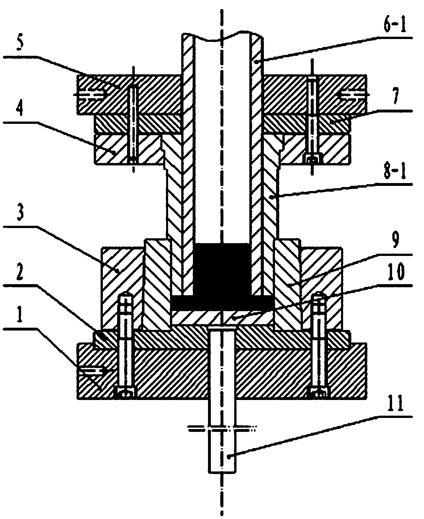
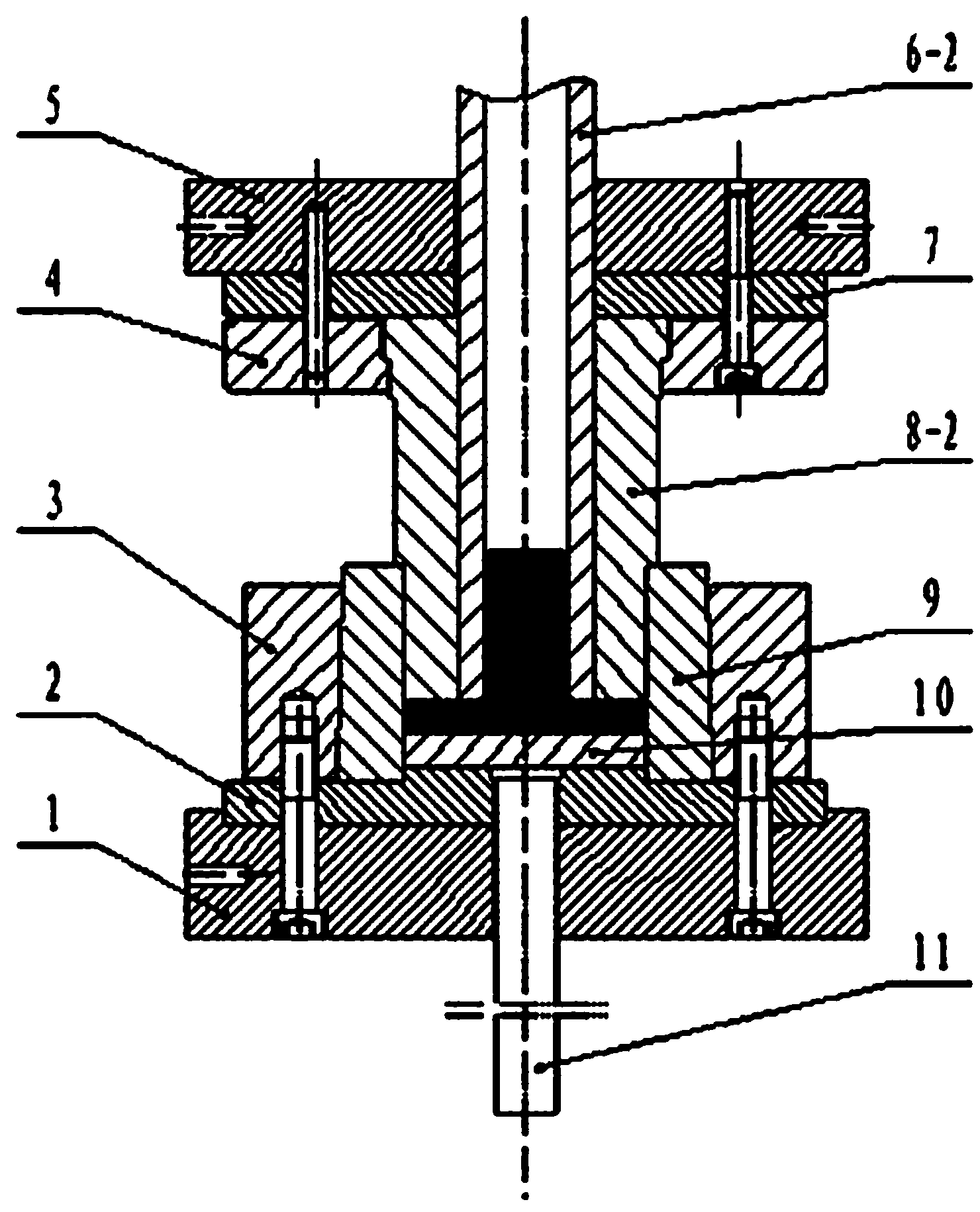
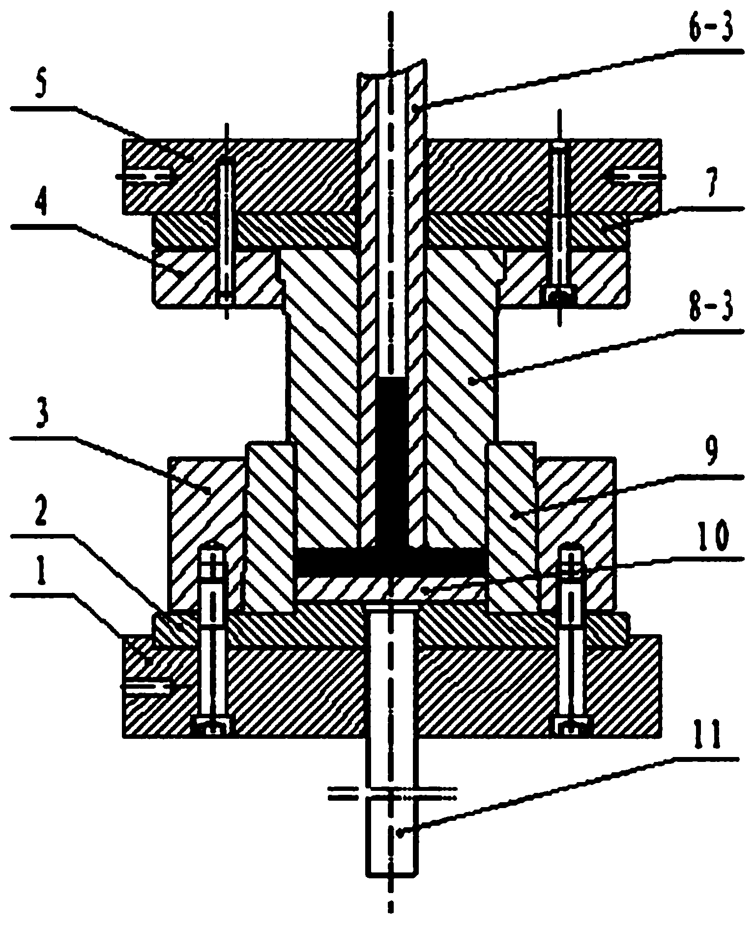
[0026] An embodiment of the extrusion forming method of a shaft part with a flange of the present invention: as Figure 1 ~ Figure 3 As shown, the extrusion molding method includes the following steps, 1) will be as figure 1 The extrusion molding die shown is installed on a double-acting hydraulic press, and the double-acting hydraulic press has two power output shafts, the outer cylinder located on the inner side and the inner cylinder located on the outer side. Figure 4 The blank with diameter D1 and height h shown is put into figure 1 In the die 9 of the extrusion molding die shown, the extrusion molding die comprises a first outer punch 8-1, the first outer punch 8-1 is provided with a central hole extending along its axial direction, and the first outer punch A step surface is arranged on the outer peripheral surface of the mold, and the step surface is set toward the side of the die. A first inner punch 6-1 is installed inside the first outer punch 8-1, and the first i...


PUM


Abstract

The invention relates to an extrusion moulding method for shaft parts with flanges, and a special extrusion mould. The adopted extrusion moulding method comprises the following steps: 1, placing a blank material in a female die, wherein the extrusion moulding mould comprises an external male die with a center hole extending along the axial direction, an internal male die is arranged in the center hole of the external male die in a penetrating manner, the hole wall of the center hole of the external male die is matched with the peripheral wall of the internal male die in a guiding sliding manner, a corresponding power output shaft of a press drives the external male die to extrude the blank material and downwards moves to reach the thickness of the flange of the required part; 2, ejecting the external male die to be kept stable on the blank material, wherein the press and a power output shaft which is in transmission connection with the corresponding internal male die drive the internal male die to downwards extrude the blank material, and the required part is formed through extrusion; and 3, completing the extrusion, wherein the press drives the external male die and the internal male die to return to eject the formed part. According to the extrusion moulding method, by adopting sequential extrusion moulding, the one-time extrusion area is small, the extrusion force required by one-time extrusion is small, the input of equipment is reduced by adopting the equipment with small tonnage, and the production cost is lowered.

Description

technical field [0001] The invention relates to the technical field of metal extrusion forming, in particular to an extrusion forming method of a shaft part with a flange and a special extrusion die. Background technique [0002] When forming shaft parts with flanges, there are generally two methods used: first, extrusion forming, that is, the process of extruding a billet with a diameter equal to the flange diameter of the desired part on a press. In extrusion molding, the larger the extrusion area, the greater the extrusion force required. Therefore, when the diameter of the flange of the part is greatly different from the diameter of the rod, the extrusion force required for one-time extrusion is larger. If it is large, the tonnage of the forming equipment that needs to be used is large and the cost of equipment investment is high; second, upsetting forming, that is, the flange with the required diameter is forged on the forging equipment from a blank with a diameter equa...

Claims


Application Information

Patent Timeline
Patent Type & Authority Applications(China)
IPC IPC(8): B21C23/18B21C25/02
Inventor 宋克兴国秀花乔艳艳张学宾赵培峰郜建新刘亚民周延军张彦敏何霞李宁宁张素霞赵亚永
Owner HENAN UNIV OF SCI & TECH
Why Eureka
Try Eureka