A Hollow Blade Push Bending Forming Process

A hollow blade and forming process technology, applied in the field of hollow blade push-bending forming process, can solve the problems of unstable effect of torsion forming process, many defects, complex equipment, etc., and achieve stable and convenient forming process, high production efficiency, and improved forming effect. Effect

Inactive Publication Date: 2015-09-09
NANJING UNIV OF AERONAUTICS & ASTRONAUTICS
View PDF6 Cites 2 Cited by
  • Summary
  • Abstract
  • Description
  • Claims
  • Application Information

AI Technical Summary

Problems solved by technology

[0004] The invention provides a new hollow blade push-bending forming process, which overcomes the problems of the existing hollow blade torsion forming process, such as unstable effect, complicated equipment, and many defects after forming, greatly improves product quality, and increases production efficiency; At the same time, the hollow blade push-bending forming process of the present invention can form a flat hollow blade blank into a complex twisted shape, so that it has the required twist angle, the forming process is stable and convenient, the speed is controllable, the deformation of each part is evenly distributed, and the production efficiency is high.

Method used


Image

  • A Hollow Blade Push Bending Forming Process
  • A Hollow Blade Push Bending Forming Process
  • A Hollow Blade Push Bending Forming Process

Examples


no. 1 example

[0041] 1. Generate the mold cavity surface according to the contour surface of the finished hollow blade.

[0042] 2. Process the mold according to the obtained mold cavity surface.

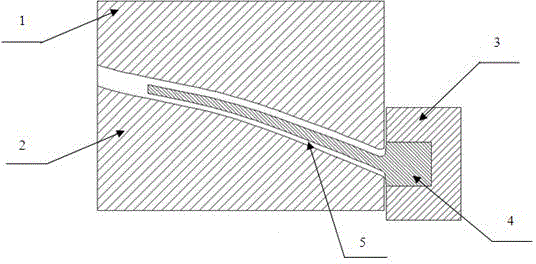
[0043] 3. The first mold half 1 is installed horizontally on the pressure head of the heat press, the second half mold 2 is installed horizontally on the working table of the heat press, and the blade 4 is installed on the chuck 3 arranged horizontally.

[0044] 4. The push bending forming process is as follows:

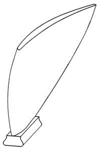
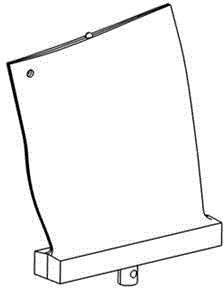
[0045] (1) The formed hollow blade blank is installed on the chuck 3 and sent into the furnace for heating;

[0046] (2) The pressure head of the hot press goes down, and the first half-mold 1 and the second half-mold 2 are closed;

[0047] (3) The chuck 3 moves towards the mold, and the blade 4 is pushed into the mold from one end of the mold cavity channel 5, and the blade is twisted and bent under the action of the mold;

[0048] (4) The pressure head of the hot press returns, and...

no. 2 example

[0051] 1. Generate the mold cavity surface according to the contour surface of the finished hollow blade.

[0052] 2. Process the mold according to the obtained mold cavity surface.

[0053] 3. Install the first half-mold 1 upright on the worktable of the heat press and fix it, the second half-mold 2 is installed upright on the movable slider of the worktable of the heat press, and the chuck 3 is installed on the pressure head of the heat press And fixed, the blade 4 is installed upright on the blade chuck 3 .

[0054] 4. The push bending forming process is as follows:

[0055] (1) Install the hollow blade blank to be formed on the chuck 3, and send it into the furnace for heating;

[0056] (2) The slider of the worktable of the hot press moves, and the first half-mold 1 and the second half-mold 2 are closed;

[0057] (3) The pressure head of the hot press moves downward, driving the blades to move towards the mold, pushing the blades from one end of the mold cavity channel...


PUM


Abstract

The invention discloses a push-bending forming process for a hollow blade. The process comprises producing a mould cavity curved surface according to a finished product hollow blade appearance curved surface; machining a mould according to the mould cavity curved surface and forming a mould cavity passage with two open sides in the mould; designing a chuck according to the blade tenon shape; fixing the chuck and the mould on a hot press; coating high-temperature lubricants on the inner surface of the mould cavity and the surface of a blade blank; mounting the blade blank on the chuck. The hot press acts, the mould is closed, the chuck drives the blade to move towards the mould to push the blade into the mould cavity from one end of the mould cavity passage, and the blade is forced to be bent under the action of the mould cavity inner surface and is subjected to torsional deformation; the mould is opened after the torsional deformation is kept for certain time, and the formed blade is dismounted. According to the process, slab hollow blade blanks can be formed into complex torsional forms and are provided with required torsion angles, the forming process is stable and convenient and fast, the speed is controllable, deformation distribution of all parts are uniform, and the production efficiency is high.

Description

technical field [0001] The invention relates to a push-bending forming process for hollow blades, which is used for forming blades with complex torsion angles, especially hollow blades. Background technique [0002] In order to meet the requirements of the aerodynamic shape of the compressor blades used in various aero-engines, the shape of the blades often has complex twist angles. This distorted curved surface shape brings great difficulties to the processing and manufacturing of the blade. Especially for blades with a hollow weight-reducing structure, the weight-reducing part is hollow inside, and the outer panel is a thin plate with a small thickness. The panels are only supported by stiffeners in local areas, and most of them are suspended. Due to its structural characteristics during the bending and torsion forming process of this type of blade, on the one hand, the torsional stiffness suddenly changes at the junction of solid and hollow, and on the other hand, its i...

Claims


Application Information

Patent Timeline
Patent Type & Authority Patents(China)
IPC IPC(8): B21D53/84B21D37/18
Inventor 陈明和吴心晨谢兰生王宁
Owner NANJING UNIV OF AERONAUTICS & ASTRONAUTICS
Why Eureka
Try Eureka