Roof Negative Pressure Exhaust Configuration

An exhaust port and negative pressure technology, applied in vertical pipes, building components, buildings, etc., can solve problems such as energy consumption, noise, vibration, etc., and achieve the effects of simple body, easy maintenance, and various installation forms

Active Publication Date: 2016-04-13
安徽骏美科技发展有限公司
View PDF6 Cites 0 Cited by
  • Summary
  • Abstract
  • Description
  • Claims
  • Application Information

AI Technical Summary

Problems solved by technology

This in turn causes energy consumption, vibration and noise, which is undesirable

Method used


Image

  • Roof Negative Pressure Exhaust Configuration
  • Roof Negative Pressure Exhaust Configuration
  • Roof Negative Pressure Exhaust Configuration

Examples


Embodiment Construction

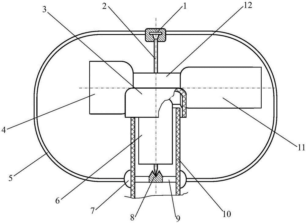
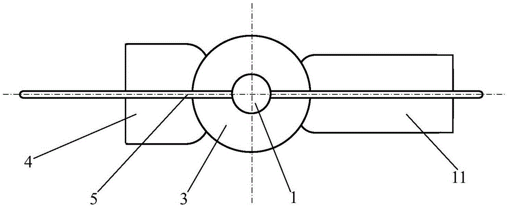
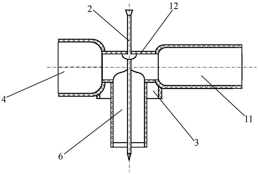
[0015] exist figure 1 , 2 In the roof negative pressure exhaust outlet configuration view shown in and 4: the roof negative pressure exhaust outlet configuration includes the roof negative pressure exhaust outlet device and frame 5, the roof pipe 10, and the roof negative pressure exhaust outlet device It is installed on the roof pipe 10 through the framework 5 . The roof negative pressure exhaust port device is composed of mandrel 2, cover 3, front windward pipe 4, lower vertical pipe 6, support beam 9, rear tailpipe 11 and neck pipe 12. The frame 5 is composed of an upper bearing structure 1 , a lower bearing structure 8 and a hoop seat structure 7 .

[0016] exist figure 1 The front view and figure 2 In the top view of the configuration of negative pressure exhaust outlets on the roof shown: the upper bearing structure 1 is fixedly installed in the center of the top section of the frame 5 of the elliptical ring structure, and the upper bearing structure 1 is rolled and...


PUM


Abstract

A roof negative pressure vent structure comprises a roof negative pressure vent device, a framework and a roof pipe. The roof negative pressure vent device is arranged on the roof pipe through the framework and is formed by a mandrel, a cover, a front windward pipe, a lower vertical pipe, a supporting beam, a rear tail pipe and a neck pipe. The framework is formed by an upper bearing structure, a lower bearing structure and a hoop base structure. The upper bearing structure is fixedly arranged at the top section center of the framework of an oval annular structure, and the upper bearing structure is matched with the top end of the mandrel in a sliding mode. The lower bearing structure is matched with the bottom end of the mandrel in a sliding mode. The lower bearing structure is fixedly arranged at the center of the supporting beam, and two ends of the supporting beam are fixedly combined with an inner wall of the roof pipe.

Description

technical field [0001] The invention relates to a negative pressure booster device for an air outlet on the roof of a building and a realization method thereof. Background technique [0002] Residential buildings, office buildings, factory buildings and other buildings are equipped with roof exhaust outlets for the overflow of silted gas. However, this method can only make the undesired silted gas overflow in a natural diffusive manner after the silted excessive amount, and cannot make the gas automatically and balancedly discharged. This status quo can cause many disadvantages, such as the gas that does not want to deposit is poured back into the living room. And if you want to make the gas continuously discharged, the usual way is to use exhaust equipment. This in turn causes power consumption, vibration and noise, which are undesirable. If the natural energy can be utilized to realize the continuous discharge of the gas that is not expected to be deposited, this is a d...

Claims


Application Information

Patent Timeline
Patent Type & Authority Patents(China)
IPC IPC(8): E04F17/02
Inventor 屈百达
Owner 安徽骏美科技发展有限公司
Why Eureka
Try Eureka