Under-pressure leaking stoppage device for oil and gas conveying pipeline

A technology for leak plugging of conveying pipelines and under pressure, which is applied to pipe components, pipes/pipe joints/fittings, mechanical equipment, etc. Eccentric wear, prevent angle deflection, ensure the effect of coaxiality and verticality

Inactive Publication Date: 2014-02-05
CHINA UNIV OF PETROLEUM (EAST CHINA)
View PDF7 Cites 12 Cited by
  • Summary
  • Abstract
  • Description
  • Claims
  • Application Information

AI Technical Summary

Problems solved by technology

[0003] Leakage plugging is a special sealing technology with high comprehensiveness, strong technicality and great responsibility. There are many ways to stop leaks. At present, the plugging technologies at home and abroad can be summarized as follows: steel belt tensioning technology, and its product shape does not need to be prefabricated. , strong adaptability to the leakage site, but it is difficult to meet the medium and high pressure transmission requirements of the oil and gas field infusion pipeline by the tensioning effect of the steel belt, so it is difficult to promote it on a large scale; plugging, and the existing various adhesives are not easy to directly repair under pressure, and a diversion device is needed to realize the adhesive repair under pressure; the injection type sealing technology can control oil and gas with a pressure above 23 MPa Leakage, but it is easy to cause impact damage to the leakage bo...

Method used


Image

  • Under-pressure leaking stoppage device for oil and gas conveying pipeline
  • Under-pressure leaking stoppage device for oil and gas conveying pipeline
  • Under-pressure leaking stoppage device for oil and gas conveying pipeline

Examples


Embodiment Construction

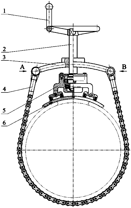
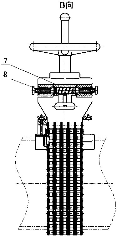
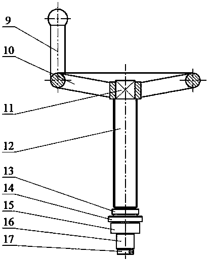
[0025] exist figure 1 and figure 2 Among them, the pressure plugging device for oil and gas transmission pipeline consists of rotating hand wheel 1, transmission shaft 2, upper slip 3, lower slip 4, pressure body 5, plugging patch 6, locking block 7 and unlocking block 8 composition. Among them, the upper part of the transmission shaft 2 is connected with the rotary hand wheel 1 through a square diameter joint, and its shaft body is connected with the upper slip 3 through the trapezoidal thread of the helical shaft, while the lower part is connected with the inner ring single rib cylindrical roller bearing and thrust roller bearing. Connected with the pressure applying body 5, the upper slip 3 and the lower slip 4 of the leakage plugging device are connected together through a pin shaft, and the leakage plugging patch 6 is connected with the pressure applying body 5 through a fastening body. In addition, the locking block 7 Put them into the locking bushing of the right cla...


PUM


Abstract

The invention provides an under-pressure leaking stoppage device for an oil and gas conveying pipeline, which has the characteristics of short operation time, small construction intensity and high leaking stoppage efficiency. The quick leaking stoppage of pipelines of different diameters under pressure or temperature or under the condition of no shutdown can be realized. The under-pressure leaking stoppage device for the oil and gas conveying pipeline comprises a rotary hand wheel, a transmission shaft, an upper slips, a lower slips, a locking block, an unlocking block, a pressing body and a leaking stoppage paster, wherein the transmission shaft is used for realizing the quick compression of the leaking stoppage paster and the self locking of the device by trapezoidal threads; the lower slips can be used for clamping pipelines of different diameters by multiple rows of roller chains; a locking pin is cooperated with the lower slips and a locking block eyehole by a spring to realize the quick locking of the device; an unlocking pin is cooperated with the upper slips and an unlocking block eyehole by a spring to realize the quick unlocking and the automatic resetting of the unlocking pin; the pressing body is provided with a cylindrical roller and a thrust roller bearing to ensure the coaxiality and the perpendicularity of the pressing body and the transmission shaft and realize the transferring of the action force; the O-shaped sealing ring of the leaking stoppage paster is pressed by the pressing body; the leaking stoppage operation can be finished by soldering the leaking stoppage paster.

Description

technical field [0001] The invention relates to a device for plugging the leakage of oil and gas pipelines in oil and gas fields, in particular to a device capable of quickly plugging up leakage under the condition of pressure and temperature or non-stop delivery. Background technique [0002] In the development of oil and gas fields, pipeline transportation is widely used in the transportation of fluids such as oil and gas. Due to manufacturing process defects, pipeline corrosion, and man-made damage, various leakages will occur in the pipeline, which not only causes energy waste, environmental pollution, and may cause cause a fire, cause an explosion and stop production, and even endanger personal safety. Plugging under pressure is the guarantee for the safe operation of oil and gas pipeline operations. The cost of plugging not only includes the cost of plugging tools and labor, but also the cost of leaking crude oil during construction. Therefore, it is necessary to study...

Claims


Application Information

Patent Timeline
IPC IPC(8): F16L55/17
CPCF16L55/1705
Inventor 刘春花刘新福
Owner CHINA UNIV OF PETROLEUM (EAST CHINA)
Why Eureka
Try Eureka