
Lateral push and pull type card swallowing self processing device and card swallowing and ejecting processing method

A technology of self-service processing and processing methods, which is applied to devices for accepting coins, processing coins or valuable banknotes, instruments, etc., to achieve the effects of improving convenience, convenient and fast card ejection, and less damage

Active Publication Date: 2014-02-05
EASTERN COMM
View PDF4 Cites 14 Cited by
  • Summary
  • Abstract
  • Description
  • Claims
  • Application Information

AI Technical Summary

Problems solved by technology

[0003] The invention provides a side push-pull type self-service processing device for swallowing cards and a handling method for cards that can be retrieved from the self-service terminal by the user and has little damage to the card, solving the problem that the existing self-service equipment can only Deficiencies in bank personnel mechanically opening the device to take out the swallowed card

Method used


Image

  • Lateral push and pull type card swallowing self processing device and card swallowing and ejecting processing method
  • Lateral push and pull type card swallowing self processing device and card swallowing and ejecting processing method
  • Lateral push and pull type card swallowing self processing device and card swallowing and ejecting processing method

Examples


Embodiment 1

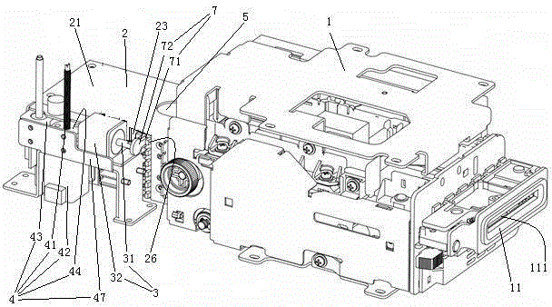
[0035] Embodiment one, see figure 1 , a side push-pull self-service processing device for swallowing cards, including a card reader 1, a card recovery box 2, a push-pull mechanism 3, a lifting mechanism 4, a plugging mechanism 7 and a control unit.

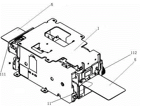
[0036] see figure 2 , the card reader 1 is the structure used on the existing automatic teller machine. The card reader 1 is provided with a card channel 11 . The outer end 111 of the card channel is in use located outside the automatic terminal. The user inserts the card 5 into the card reader 1 from the outer end 111 of the card channel. Card 5 just outputs from the inner end 112 of card channel when card is swallowed.

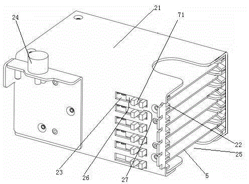
[0037] see image 3, The card recovery box 2 includes a housing 21 and 6 card holding slots 22 arranged in the housing. The 6 card holding slots 22 are distributed along the up and down direction. The card holding slot 22 extends along the front-to-back direction. The front end of the housing 21 is provi...

Embodiment 2

[0053] Embodiment two, the difference with embodiment one is:

[0054] see Figure 7 and Figure 8 , put card slot 22 and only have three pairs. The slot 27 defines a through hole 271 . The through hole 271 penetrates from the slot 71 to the bottom 272 of the card slot. A pressing rod 273 passes through the through hole 271 . A suction cup 274 is provided at one end of the pressing rod 273 facing the inside of the housing 21 . An end of the pressing rod 273 away from the inside of the housing 21 extends into the slot 71 . The pressing rod 273 is provided with a vacuum breaking channel 275 . The vacuum breaking channel 275 extends from the inside of the suction cup 274 to the outer end of the pressing rod 273 . The end of the bayonet pin 72 is provided with an upper introduction surface 721 , a lower introduction surface 722 and a sealing portion 73 .

[0055] During use, when the card holder slot 22 is aligned with the card channel, the bayonet pin 72 is inserted into ...

Embodiment 3

[0056] Embodiment three, the difference with embodiment two is:

[0057] see Figure 9 , The plug-in mechanism 7 is made up of a latch 74 and a jack 75 . The pin 74 is disposed at an outer end of the slot 27 . The insertion hole 75 is disposed on the push-pull rod 31 . The insertion hole 75 extends in the left-right direction. The sealing portion 73 is disposed on the bottom wall of the insertion hole 75 . The push-pull mechanism 3 also includes a socket moving mechanism 33 . Socket moving mechanism 33 is a double-stroke cylinder. The cylinder block of the double stroke cylinder is connected to the base frame 47 . The drive mechanism 32 is connected to the piston rod of the double stroke cylinder.

[0058] During use, when the card slot 22 is aligned with the card channel, if the card slot 27 is not required to drive the card 5, the control unit moves the socket moving mechanism 33 for a stroke, and the socket 75 moves toward the latch 74 to be sleeved on the latch 74 ...


PUM


Abstract

The invention relates to a self-service device for using a card to operate. The invention provides a lateral push and pull type card swallowing self processing device through which a user can take a swallowed card from a self-service terminal and a card swallowing and ejecting processing method. The device comprises a card reader, a card withdrawing box with a card channel, a push and pull mechanism, a lifting mechanism and a control unit. The card withdrawing box comprises a shell and a plurality of card placing grooves which are arranged in the shell and distributed along up and down directions and can be aligned with the inner end of the card channel. The side of the shell is provided with a plurality of sliding holes which pass through the card placing groove in one to one correspondence and extend along the extending direction of the card placing grooves. Clamping grooves which are aligned with card placing channels are slidingly connected with the sliding holes. The push and pull mechanism comprises a push and pull rod and a driving mechanism which drives the push and pull rod to translate along the extending direction of the card placing grooves. A plug-in mechanism is arranged between the push and pull rod and the clamping grooves. The shell is in rise-fall connection next to the push and pull rod through the lifting mechanism. A detect in the fact that the bank staff rigidly opens the device to take a swallowed card out is solved.

Description

technical field [0001] The invention relates to a self-service device operated by using a card, in particular to a side push-pull type self-service card processing device and a card processing method. Background technique [0002] In the process of using the automatic teller machine, the bank card will be inserted into the card reader as needed, and after the operation is completed, the card reader will spit out the card for the user to retrieve. A kind of existing self-service equipment is disclosed in the patent document whose Chinese patent number is 2011200732143, the authorization announcement date is September 7, 2011, and the title is "dual-code alarm card reader device". Occasionally, there will be abnormal situations in the self-service equipment, resulting in card swallowing, such as the following two situations: the user forgets to take out the card and leaves after the operation. At this time, in order to prevent the card from being taken away by others, the ...

Claims


Application Information

Patent Timeline
IPC IPC(8): G07D11/00
Inventor 吴祖江吴晨林秋明
Owner EASTERN COMM
Learn More