
Radio frequency power amplifier module in train intelligent monitoring network node

An intelligent monitoring and network node technology, applied in impedance networks, multi-terminal-pair networks, electrical components, etc., can solve the problems of inability to guarantee monitoring nodes, data transmission and reception delay, high output power, etc., to reduce co-frequency interference and improve reliability. sex, the effect of reducing reflections

Active Publication Date: 2014-02-05
DALIAN JIAOTONG UNIVERSITY
View PDF4 Cites 1 Cited by
  • Summary
  • Abstract
  • Description
  • Claims
  • Application Information

AI Technical Summary

Problems solved by technology

[0002] At present, the known data transmission of train monitoring nodes adopts two methods: wired transmission of the on-board equipment itself and wireless transmission between the train and the monitoring center. In wireless transmission, the point-to-point radio frequency mode between the train and the monitoring center is usually used to send and receive data. This mode has a simple structure and is convenient. implementation; but when the train enters tunnels, mountain shelters and other environments, due to signal attenuation, the existing monitoring nodes cannot guarantee sufficient output power to ensure data transmission
At the same time, because the design structure of its communication mode is simple, the same-frequency interference generated by the output signal is not suppressed, which will lead to delays and errors in data transmission and reception.

Method used


Image

  • Radio frequency power amplifier module in train intelligent monitoring network node
  • Radio frequency power amplifier module in train intelligent monitoring network node
  • Radio frequency power amplifier module in train intelligent monitoring network node

Examples


Embodiment Construction

[0023] The present invention will be further described below in conjunction with the accompanying drawings.

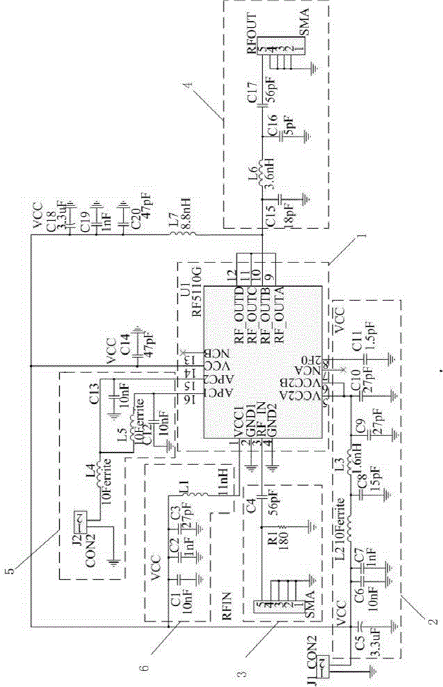
[0024] Such as figure 1 As shown, a radio frequency power amplifier module in a train intelligent monitoring network node includes a main chip 1, a power supply circuit 2, a radio frequency input circuit 3, a radio frequency output circuit 4, a drive control circuit 5 and a preamplifier circuit 6, the described The main chip 1 is connected to the power supply circuit 2, the radio frequency input circuit 3, the radio frequency output circuit 4, the drive control circuit 5 and the preamplifier circuit 6 respectively;

[0025] The power supply circuit 2 provides power for the main chip 1, the preamplifier circuit 6 and the drive control circuit 5;

[0026] The radio frequency input circuit 3 includes a radio frequency input port and a filter circuit. The filter circuit is composed of a resistor R1 and a capacitor C4. One end of the capacitor C4 is connected to the main ...


PUM


Abstract

The invention discloses a radio frequency power amplifier module in a train intelligent monitoring network node. The radio frequency power amplifier module in the train intelligent monitoring network node comprises a main chip, a power supply circuit, a radio frequency input circuit, a radio frequency output circuit, a driving control circuit and a pre-amplification circuit, wherein the main chip is respectively connected with the power supply circuit, the radio frequency input circuit, the radio frequency output circuit, the driving control circuit and the pre-amplification circuit. On the research background of the train wireless sensor network technology, in order to guarantee normal communication after a train enters the environment with weakened signals such as a tunnel or a mountainous area, the radio frequency power amplifier module guarantees large enough output power through amplification and guarantees normal transmitting and receiving of communication data. The radio frequency power amplifier module in the train intelligent monitoring network node guarantees that in the environment with weakened signals, a monitoring network carries out real-time and continuous monitoring on the operation state of vehicle-mounted equipment, and reduces safety risks when the train runs. The radio frequency power amplifier module in the train intelligent monitoring network node can restrain same-frequency signals of an output end, prolongs the communication distance, improves the reliability of data transmission, and well guarantees correct transmission of monitoring data.

Description

technical field [0001] The invention relates to a radio frequency power module circuit, in particular to a radio frequency power amplifier module in a train intelligent monitoring network node. Background technique [0002] At present, the known data transmission of the train monitoring node adopts two methods: wired transmission of the on-board equipment itself and wireless transmission between the train and the monitoring center. In wireless transmission, the point-to-point radio frequency mode between the train and the monitoring center is usually used to send and receive data. This mode has a simple structure and is convenient. implementation; but when the train enters tunnels, mountain shelters and other environments, due to the attenuation of the signal, the existing monitoring nodes cannot guarantee sufficient output power to ensure data transmission. At the same time, because the design and structure of its communication mode are simple, the same-frequency interferen...

Claims


Application Information

Patent Timeline
IPC IPC(8): H03H7/01H03H7/38
Inventor 陈少华赵小耕曾洁张巍
Owner DALIAN JIAOTONG UNIVERSITY
Learn More