Spring contact pin arrangement

A pin-in device and pin-in technology, which are applied to measurement devices, use mechanical devices to transmit sensing components, instruments, etc., can solve the problems of non-existence, no electrical switch path, and inability to explain whether the test object is defective, etc. Space saving, low flexibility effect

Inactive Publication Date: 2014-02-05
FEINMETALL
View PDF5 Cites 10 Cited by
  • Summary
  • Abstract
  • Description
  • Claims
  • Application Information

AI Technical Summary

Problems solved by technology

Commonly used spring contact pins (i.e. non-switching pins) can make electrical contact with the test object, but do not have an electrical switching path, they can only be used for electrical testing and only in the above-mentioned roughly described manner (test object presence or test object not present) for presence testing, where electrical errors (e.g. absence of electrical potential) do not tell whether the test object is defective or whether it is not present

Method used


Image

  • Spring contact pin arrangement
  • Spring contact pin arrangement
  • Spring contact pin arrangement

Examples


Embodiment Construction

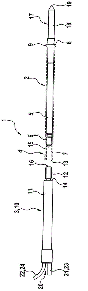
[0029] figure 1 Shown is a spring contact pin arrangement 1 with spring contact pins 2 , a position sensor 3 and a transparently shown coupling sleeve 4 . Most of the spring contact pins 2 are located inside the coupling sleeve 4 ; the position sensor 3 is in a state not connected to the coupling sleeve 4 , ie in the unmounted position. During operation, ie when testing an electrical test object (not shown) with the spring contact pin arrangement 1 , the spring contact pins 2 are held by the coupling sleeve 4 on a support of the test device. For this purpose, the pin housing 5 of the spring contact pin 2 has an external thread 6 which is screwed into an internal thread 7 of the coupling sleeve 4 . This screwing in takes place until the end face 8 of the coupling sleeve 4 touches the flange 9 of the pin housing 3 . Such as figure 1 As shown, the position sensor 3 is designed as a position sensor pin 10 and has a sensor housing 11 with an external thread 12 which can thus be ...


PUM


Abstract

The invention relates to a spring contact pin arrangement having a spring contact pin that comprises a pin housing in which a contact element is mounted so as to be longitudinally displaceable and is loaded by a spring device acting opposite to a displacement direction, wherein the contact element is connected to at least one first interface of the spring contact pin arrangement and protrudes from the pin housing with a contact region for electrical contacting of an electric test item. According to the invention the spring contact pin arrangement comprises a position sensor, wherein the contact element, in order to transfer the stroke thereof, is connected to a displaceable sensor element of the position sensor detecting the stroke position of the contact element.

Description

technical field [0001] The invention relates to a spring contact pin arrangement having a spring contact pin with a pin housing in which a contact element is mounted so as to be displaceable in the longitudinal direction and is controlled by a force acting relative to the direction of movement. The spring arrangement is loaded with force, wherein the contact element is electrically connected to the at least one first interface of the spring contact pin arrangement and protrudes outwards from the contact housing through the contact area to make electrical contact with the electrical test object. Background technique [0002] Spring contact pin arrangements of the type described above are known. The spring contact pins of the spring contact pin device are used to make electrical contact with electrical test objects in order to test their performance. By interrogating the electrical contacts of the spring contact pins, a yes / no description is sufficient for the presence testin...

Claims


Application Information

Patent Timeline
Patent Type & Authority Applications(China)
IPC IPC(8): G01R1/067
CPCG01R1/06722G01R1/06794G01D5/02
Inventor 约尔格·布尔戈尔德
Owner FEINMETALL
Why Eureka
Try Eureka