Supercharge Your Innovation With Domain-Expert AI Agents!

Devices and systems including enabling circuits

A circuit and output circuit technology, applied in the field of semiconductor memory, can solve the problems of unsatisfactory use of input/output buffers and high voltage

Active Publication Date: 2017-06-09
MICRON TECH INC
View PDF3 Cites 0 Cited by
  • Summary
  • Abstract
  • Description
  • Claims
  • Application Information

AI Technical Summary

Problems solved by technology

In some instances, the externally supplied voltage used to generate the boosted voltage for read and program operations may be too high to be desirable for use by the input / output buffers

Method used


Image

  • Devices and systems including enabling circuits
  • Devices and systems including enabling circuits
  • Devices and systems including enabling circuits

Examples


Embodiment Construction

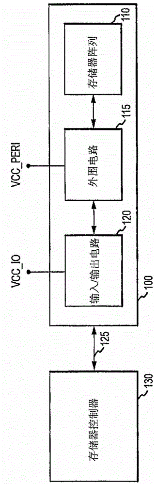
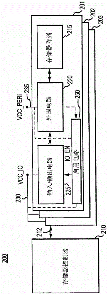
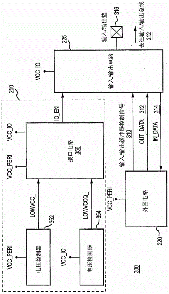
[0026] As described above, memory devices can utilize multiple externally supplied voltage supplies. As will be described further herein, one of those externally supplied voltages can be disabled (eg, disconnected, disconnected, turned off, or otherwise rendered unavailable) during operation of the memory device. In some instances, this can save power. Embodiments of the present invention reduce or eliminate leakage currents that would otherwise arise when the voltage supply is disabled. While some embodiments of the present invention may provide this advantage or solve the aforementioned problems, the advantages and problems are provided for ease of illustration, and it is to be understood that some examples of the present invention may not provide the benefits described herein. or address any or all of the shortcomings identified in the art. Embodiments of the invention include several systems. As used herein, a system may refer to a memory system or other systems. A sys...


PUM


Abstract

This disclosure describes examples of devices and systems that include enabling circuits. Two voltage supplies can be used to operate different parts of the device, including peripheral circuits and I / O circuits. When the voltage supply to the peripheral circuits of one or more devices is disabled, the I / O circuits of the devices may be disabled. In some examples, power can be advantageously saved in part by eliminating or reducing the DC current path through the I / O circuitry.

Description

technical field [0001] Embodiments of the invention relate generally to semiconductor memory, and more particularly describe an example of an interface circuit for a dual supply voltage memory. Background technique [0002] With the increasing popularity of electronic devices such as laptop computers, portable digital assistants, digital cameras, mobile phones, digital audio players, video game consoles, etc., the demand for non-volatile memory is also rising. Non-volatile memory comes in various types, including flash memory. Flash memory is widely used today for fast information storage in electronic devices such as those mentioned above. Flash memory cells are generally programmed by storing charge on a floating gate. Thereafter, charge can remain on the gate for an infinite period, even after power has been removed from the flash memory device. Thus, flash memory devices are non-volatile. [0003] Charge is stored on the floating gate by applying appropriate voltages...

Claims


Application Information

Patent Timeline
Patent Type & Authority Patents(China)
IPC IPC(8): G11C7/10G11C5/14
CPCG11C5/143G11C7/1066G11C7/1093G11C7/22G11C7/10G11C7/1087
Inventor 丹沢彻阿里·法伊兹·扎尔林·加莱姆
Owner MICRON TECH INC
Features
  • R&D
  • Intellectual Property
  • Life Sciences
  • Materials
  • Tech Scout
  • Unparalleled Data Quality
  • Higher Quality Content
  • 60% Fewer Hallucinations
Learn More