Method and apparatus for identifying features of an object and tomography imaging

A technology of tomographic images and objects of interest. It is used in eye testing equipment, image enhancement, image analysis, etc. It can solve the problems of low resolution, inability to detect, and small number of 3D data.

Inactive Publication Date: 2014-02-12
CANON KK
View PDF6 Cites 6 Cited by
  • Summary
  • Abstract
  • Description
  • Claims
  • Application Information

AI Technical Summary

Problems solved by technology

[0008] Examination area includes optic disc, but cannot be detected due to low resolution of 3D data (e.g., low number of B-scans and / or A-scans)

Method used


Image

  • Method and apparatus for identifying features of an object and tomography imaging
  • Method and apparatus for identifying features of an object and tomography imaging
  • Method and apparatus for identifying features of an object and tomography imaging

Examples


Embodiment Construction

[0043] In the first embodiment, an image of the retina is captured by the second imaging device simultaneously with OCT data acquisition. In the present embodiment, the second imaging device includes a scanning laser ophthalmoscope (SLO), which obtains an image of the retina, but it should be understood that the present invention is not limited thereto. Any suitable imaging device suitable for obtaining images of features of interest may be used. For example, for retinal imaging to identify the optic disc, a fundus camera or other similar devices suitable for retinal imaging can be used.

[0044] The captured positions of specific features of the retina are obtained based on the captured images.

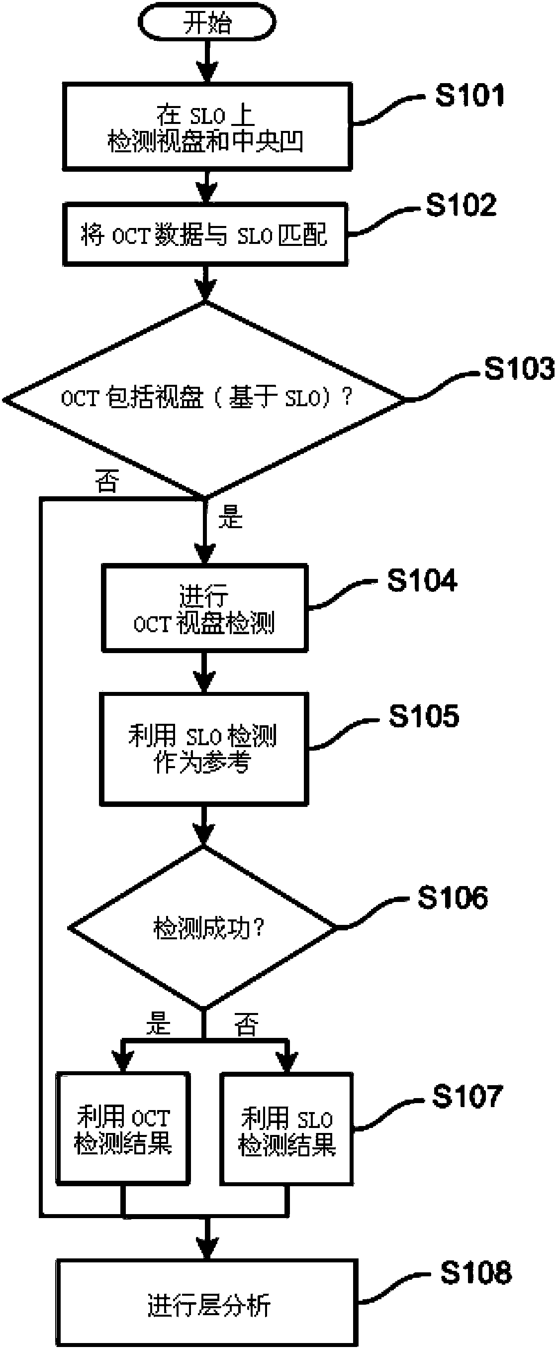
[0045] refer to figure 1 , shows a flowchart of an embodiment of the present invention. In general, optic disc positions are first detected on additional images. This can be achieved by applying common image processing techniques such as edge detection filters, transforms to dete...


PUM


Abstract

The present invention relates to a method and apparatus for determining the position of a feature of an object under test in a tomography image. The method comprises: - determining characterizing points, in an additional image, of a feature of the object of interest; - determining position data relating to the feature in the additional image based on the detected characterizing points; and - identifying a feature of the object of interest in the tomography image, wherein the determined position data in the additional image is used to guide the identification. The invention also relates to a computer readable medium which upon execution by a processor configures a computer to perform the method.

Description

technical field [0001] The invention relates to a method and a device for determining the position of a feature of a measured object in a tomographic image in an imaging system using optical coherence tomography (OCT). In particular, but not exclusively, the invention relates to the detection of boundaries between certain layers of the eye during optical tomographic data acquisition, especially OCT scans, and the detection of certain eye-specific defects such as the optic disc (blind spot) or fovea. feature. Background technique [0002] Optical coherence tomography (OCT) is a technique for high-resolution cross-sectional imaging that can provide images of tissue structures. OCT is a method of determining the interference of the scattering profile of a sample in the direction of the OCT beam. Each scatter profile is called an axial scan, or A-scan. A series of A-scans across the structure enables the reconstruction of sections in planes through the anterior or posterior p...

Claims


Application Information

Patent Timeline
Patent Type & Authority Applications(China)
IPC IPC(8): A61B3/14A61B3/12
CPCG06K9/4671G06T2207/30041G06T7/0097G06T2207/20221G06T2207/10101G06T7/174
Inventor L·品特尔K·彼得罗夫斯基M·波佩克W·苏拉K·左克夫斯基
Owner CANON KK
Why Eureka
Try Eureka