Method for identifying an individual

A technology of personnel and line of sight direction, applied in the field of personnel identification, can solve problems such as misuse of personnel identification system, achieve high reliability and credibility, and improve the effect of identification ability

Pending Publication Date: 2017-02-22
ROBERT BOSCH GMBH
View PDF5 Cites 0 Cited by
  • Summary
  • Abstract
  • Description
  • Claims
  • Application Information

AI Technical Summary

Problems solved by technology

[0003] However, this type of person identification system has the risk of being misused, for example by bringing a picture of an authorized person into the field of view of a camera, so that person identification is based only on images and not on real people

Method used


Image

  • Method for identifying an individual

Examples


Embodiment Construction

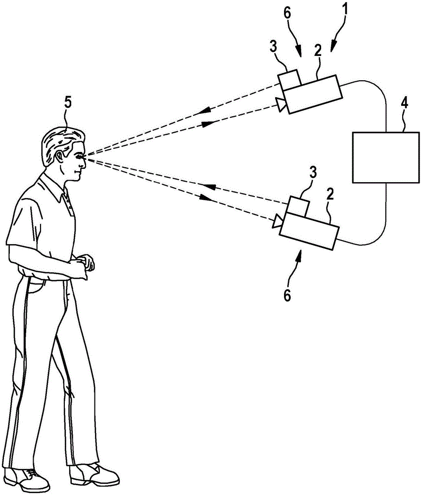
[0018] The person detection system 1 includes two cameras 2 , each of which is associated with a lighting unit 3 , and a computing unit 4 for evaluating received data and signals. On the extension of their axes, the two cameras 2 and the associated lighting unit 3 have a point of intersection at which the head 5 of the person to be detected is located. The person recognition system 1 can be used, for example, as a driver authorization control in a vehicle or as a building access control.

[0019] Advantageously, the two cameras 2 are designed identically, for example infrared cameras or video cameras. It is also expedient to design the lighting units 3 uniformly, which can each be embodied as an infrared lighting unit (preferably in the near-infrared range) or optionally as a lighting unit in the visible light range. Each camera 2 belongs to a camera system, and in addition, each camera and the lighting unit 3 together form a line-of-sight recognition unit 6 . Computing unit...


PUM


Abstract

In a method for identifying an individual, an individual is recognized using a camera, an individual being positively identified only if the position of the eyes of the individual is identified in a viewing direction-recognizing unit.

Description

technical field [0001] The invention relates to a method for identifying persons, for example as driver authorization control in a vehicle or as building access control. Background technique [0002] Video-based people recognition systems are known which are used for access control of buildings and which compare images of people recorded by a video camera with stored reference images. Access is granted if the captured image agrees with the reference image on a set of characteristics. [0003] However, such person recognition systems run the risk of being misused, for example by bringing a picture of an authorized person into the field of view of a camera, so that person recognition is based only on images and not on real people. Contents of the invention [0004] The object of the invention is to carry out the identification of persons by means of simple measures, in which case the risk of misuse is reduced. [0005] This object is solved according to the invention by th...

Claims


Application Information

Patent Timeline
Patent Type & Authority Applications(China)
IPC IPC(8): G06K9/00
CPCG06V40/166G06V40/165G06V40/19G06V40/193G06V40/40G06V40/197G06V20/59G06V40/70G06T7/70G06T2207/30196
Inventor H·蒂恩
Owner ROBERT BOSCH GMBH
Why Eureka
Try Eureka