Pipe sizing sleeve device
A technology for sizing sleeves and pipes, which is applied to tubular objects, other household appliances, and other household appliances. It can solve the problems of easy retention of cooling water, faster water flow, and slower heat dissipation, so as to reduce production costs and speed up water flow. , the effect of improving the quality
- Summary
- Abstract
- Description
- Claims
- Application Information
AI Technical Summary
Problems solved by technology
Method used
Image
Examples
Embodiment 1
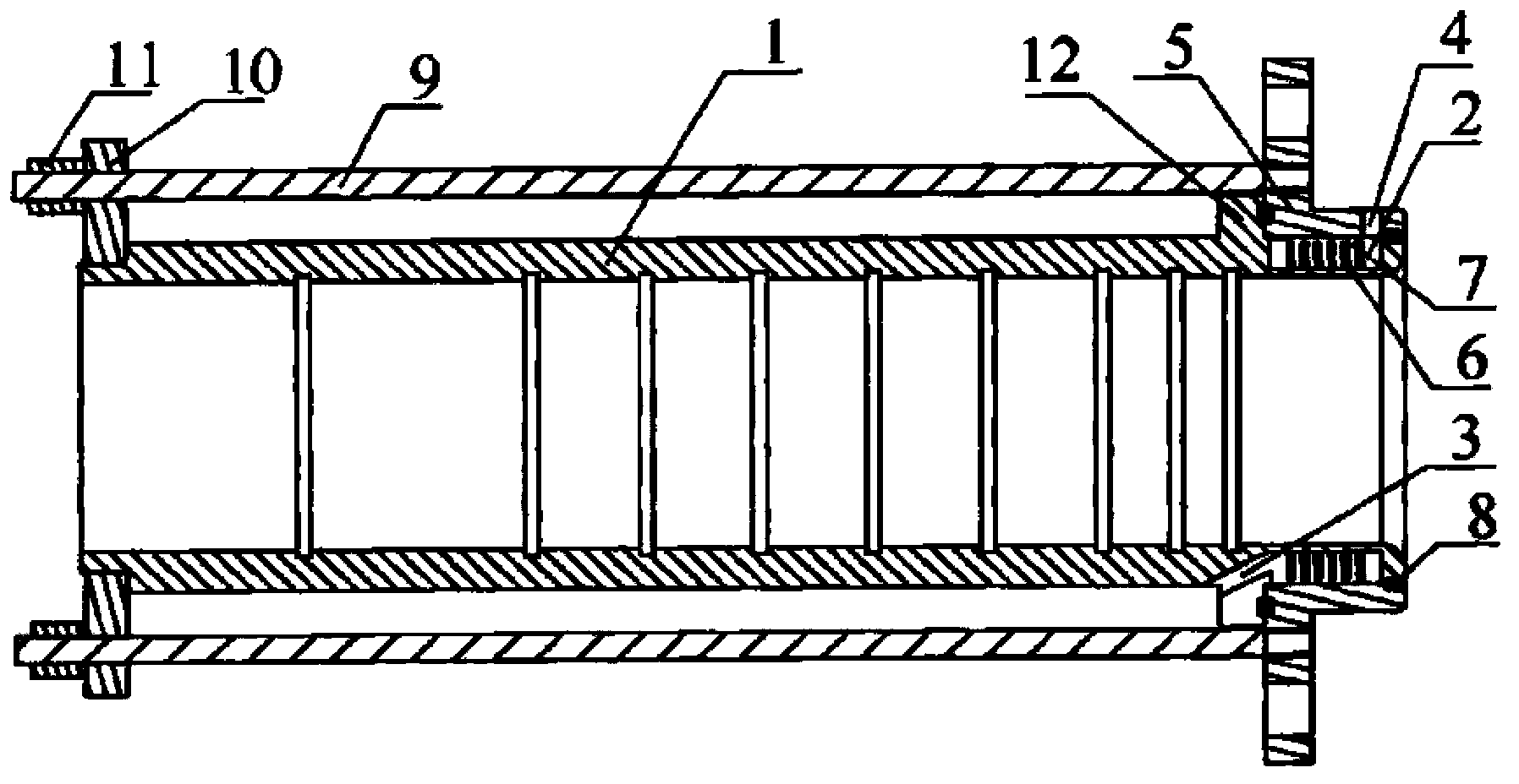
[0015] Example 1: as figure 1 As shown in the figure, the pipe sizing sleeve device of the present invention includes: a sizing sleeve main body 1 and a fixing sleeve 5; one end of the sizing sleeve main body 1 is provided with a diversion groove 2 and a water outlet 3, and the water outlet is used to facilitate the diversion of water. The cooling water circulating in the groove 2 is led out; the fixing sleeve is used to prevent the cooling water in the diversion groove 2 from flowing out, so that the guiding groove 2 forms a closed cooling water system; the fixing sleeve 5 is arranged on the main body 1 of the sizing sleeve and has The water inlet 4 communicated with the guide groove 2; the water inlet can facilitate the injection of cooling water into the guide groove 2. In order to prevent the cooling water from overflowing, a sealing ring 8 is also provided between the contact surface of the fixed sleeve 5 and the main body 1 of the sizing sleeve.
[0016] In order to bet...
Embodiment 2
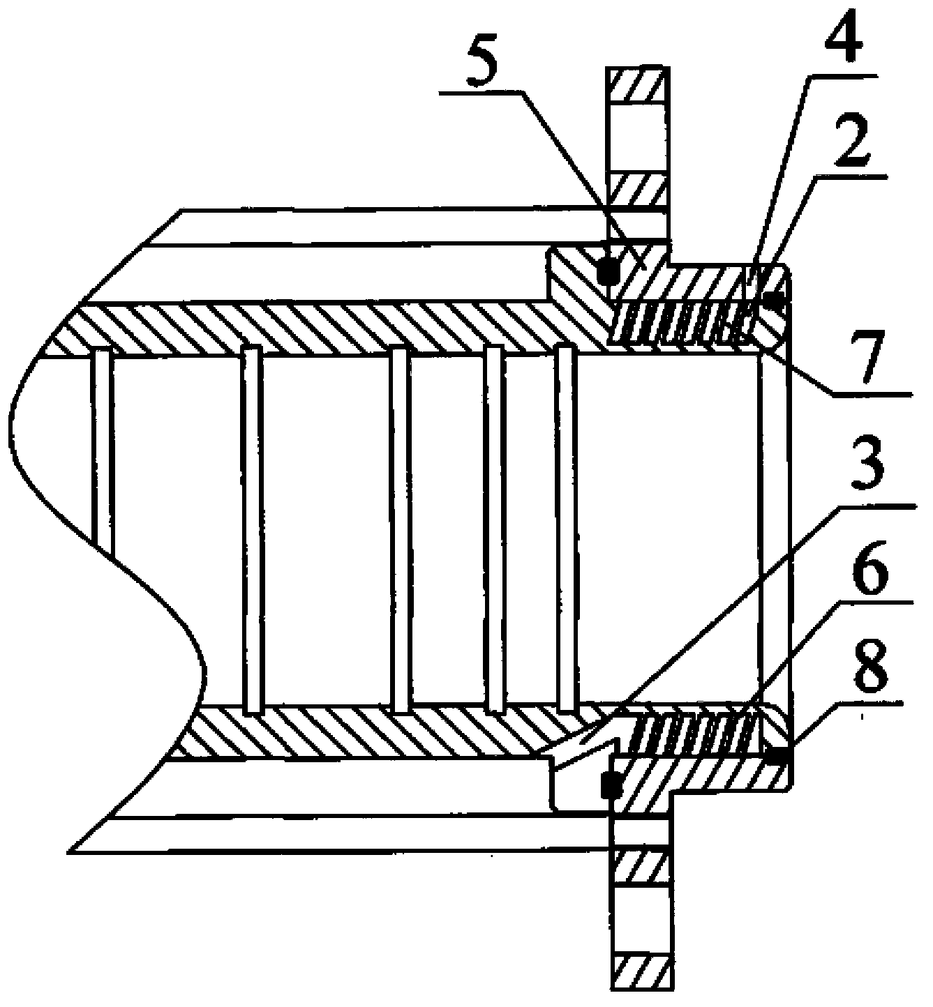
[0021] like figure 2 As shown, compared with Embodiment 1, the overall structure of this embodiment is basically the same, and the difference only lies in the structure of the heat sink 6 . As shown in the figure, in this embodiment, the heat sink 6 adopts a piece of metal sheet and is arranged in a spiral shape along the bottom surface of the guide groove 2 , so that a single thread is formed inside the guide groove 2 .
[0022] Since the metal sheet is spirally arranged inside the guide groove 2, the circulating water flow channel 7 formed inside the metal sheet is also spirally arranged, that is, the circulating water flow channel 7 is a spiral groove. In order to increase the flow rate of cooling water, the helical groove is preferably configured as a rectangular thread shape. Since the metal sheet forms a single thread inside the diversion groove 2, only one circulating water flow channel 7 is formed inside the heat sink 6 formed by the metal sheet. In order to ensure t...
Embodiment 3
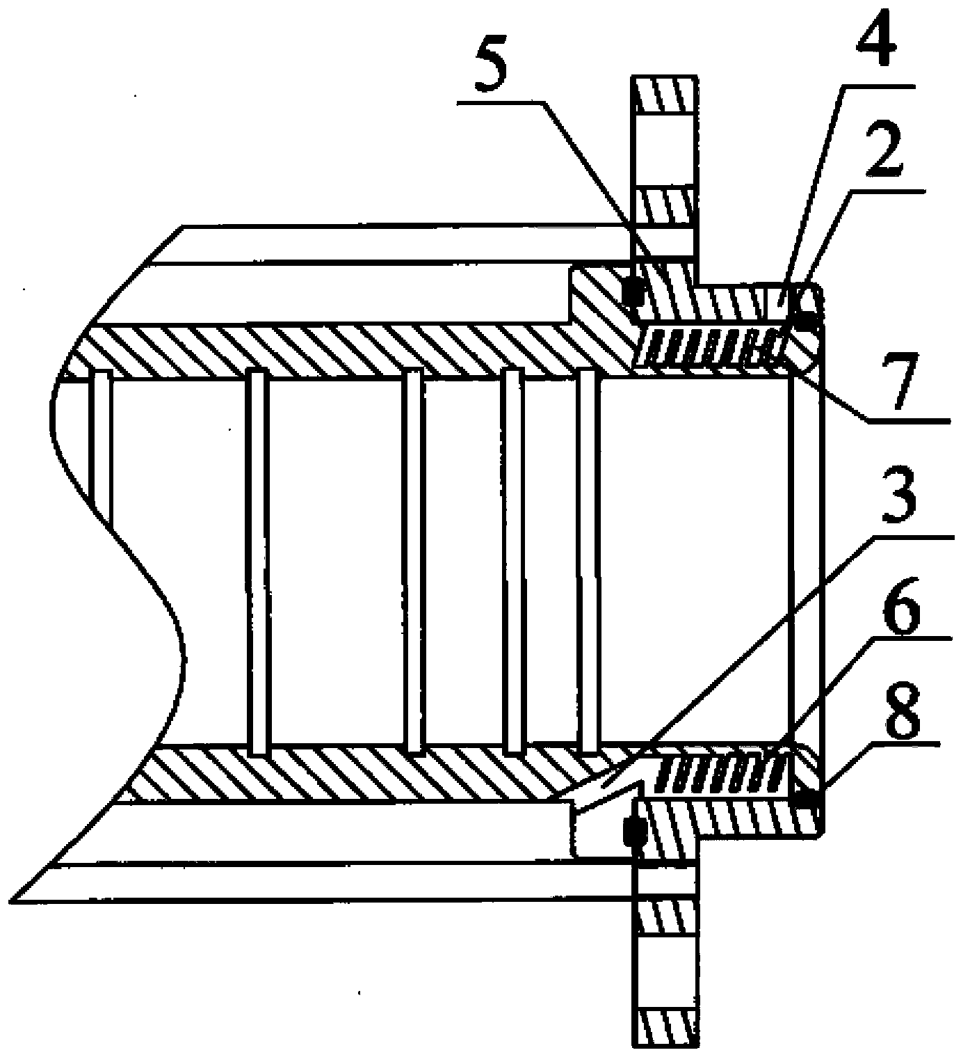
[0024] like image 3 As shown, compared with Embodiment 2, the overall structure of this embodiment is basically the same, the difference is that the number of metal sheets arranged inside the diversion groove is more than 2, that is, these metal sheets are all along the direction of the diversion groove 2. The bottom surface is helically arranged to form a multi-start thread shape. Correspondingly, more than two circulating water flow channels 7 are formed inside the heat sink 6 .
[0025] Therefore, it can be deduced that when several pieces of metal sheets are spirally arranged along the bottom surface of the guide groove 2 in the guide groove 2, several circulating water flow channels 7 are correspondingly formed inside it.
[0026] The present invention has the following advantages:
[0027] (1) The structure is simple, the cost is low, and the use is convenient.
[0028] (2) There are radiating fins inside the diversion groove, thereby improving the heat dissipation e...
PUM
 Abstract
Description
Claims
Application Information
 - R&D
- Intellectual Property
- Life Sciences
- Materials
- Tech Scout
- Unparalleled Data Quality
- Higher Quality Content
- 60% Fewer Hallucinations
Browse by: Latest US Patents, China's latest patents, Technical Efficacy Thesaurus, Application Domain, Technology Topic, Popular Technical Reports.
© 2025 PatSnap. All rights reserved.Legal|Privacy policy|Modern Slavery Act Transparency Statement|Sitemap|About US| Contact US: help@patsnap.com


