
Heat exchange jacekt

A heat exchange sleeve and sleeve technology, which is applied in the direction of gaseous chemical plating, metal material coating process, coating, etc., can solve the problem of large temperature difference of heat exchange sleeve, uneven temperature distribution of heat exchange sleeve, and uneven vapor deposition reaction And other issues

Active Publication Date: 2014-02-12
YINGLI ENERGY CHINA
View PDF4 Cites 0 Cited by
  • Summary
  • Abstract
  • Description
  • Claims
  • Application Information

AI Technical Summary

Problems solved by technology

The heat exchange circuit in the common heat exchange jacket is usually a single-lead helical type, that is, a spiral restrictor plate is added in the cavity of the heat exchange jacket to extend the running route of the heat carrier; One end of the sleeve enters and the other end flows out, resulting in a large temperature difference between the two ends of the heat exchange sleeve, and uneven temperature distribution in the circumferential direction of the heat exchange sleeve, resulting in inconsistent heat exchange effects on the bottom surface of the deposition, resulting in uneven distribution of the thermal field on the bottom surface of the deposition. As a result, the vapor deposition reaction cannot be carried out uniformly

Method used


Image

  • Heat exchange jacekt
  • Heat exchange jacekt
  • Heat exchange jacekt

Examples


Embodiment Construction

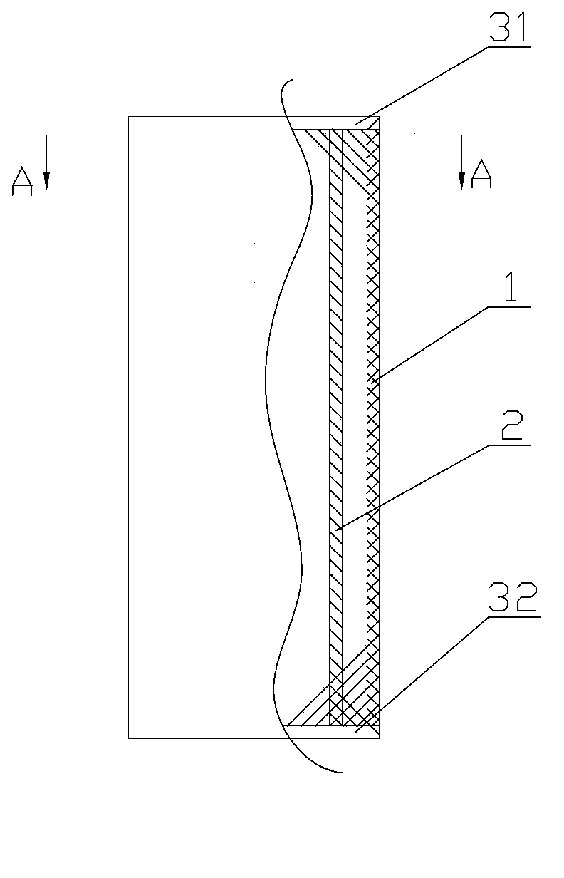
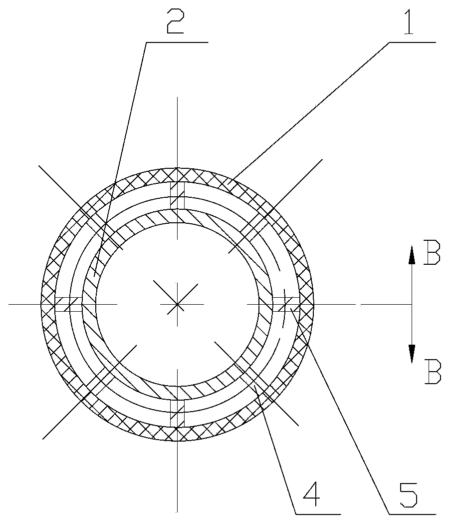
[0022] The core of the present invention is to provide a heat exchange sleeve, which can reduce the temperature difference between the two ends during operation, so that the circumferential temperature distribution of the heat exchange sleeve is uniform, thereby ensuring uniform distribution of the thermal field on the surface of the deposition bottom, and uniform vapor deposition reaction. conduct.

[0023] In order to enable those skilled in the art to better understand the solution of the present invention, the present invention will be further described in detail below in conjunction with the accompanying drawings and specific embodiments.

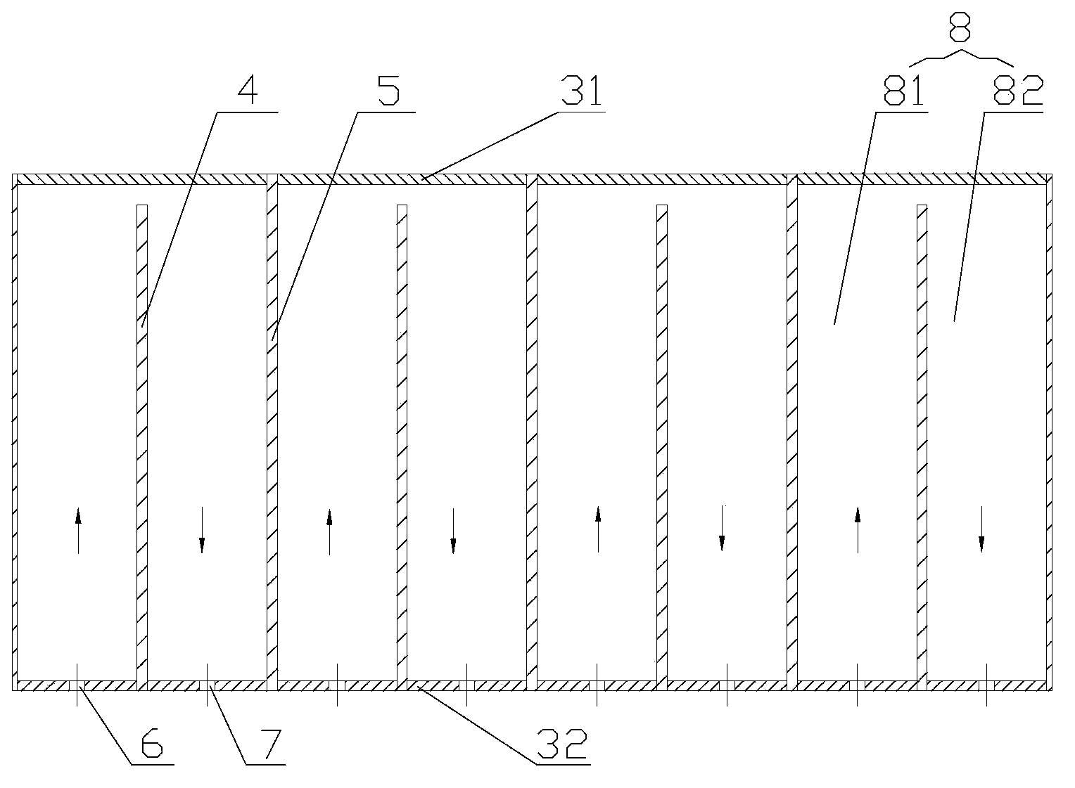
[0024] It should be pointed out that the localizers such as up, down, left and right involved in this article are based on figure 1 and image 3 The components are located in the drawings and the positions of the components are defined only for the clarity and convenience of expressing the technical solution. It should be understood ...


PUM


Abstract

The invention discloses a heat exchange jacket which comprises a sleeve formed by an outer shell and an inner shell as well as an upper end cover and a lower end cover which are arranged at both ends of the sleeve, wherein at least one current-limiting plate and at least one partitioning plate are arranged in an interlayer of the sleeve; one end of the current-limiting plate is connected with the lower end cover and a predetermined distance is maintained from the other end of the current-limiting plate to the upper end cover; the lower end cover is provided with an inlet and an outlet which are formed in both sides of the current-limiting plate. According to the heat exchange jacket, a single lead heat exchange loop of a heat carrier is changed to a double lead heat exchange loop, so that the inlet and the outlet of the heat carrier are formed in the same side of the heat exchange sleeve, thereby avoiding the problem that the temperature difference between two ends of the heat exchange jacket caused by the single lead heat exchange loop is large. Temperatures are uniformly distributed in the periphery of the heat exchange sleeve, so that the thermal fields are uniformly distributed on the bottom deposition surface, and vapor deposition reaction can be uniformly carried out.

Description

technical field [0001] The invention relates to the field of chemical vapor deposition, in particular to a heat exchange jacket for chemical vapor deposition. Background technique [0002] Chemical vapor deposition is a process technology in which reacting substances undergo chemical reactions under gaseous conditions, and solid substances are deposited on the surface of a heated solid substrate to obtain solid materials. Chemical vapor deposition is widely used in the purification of substances, the development of new crystals, and the deposition of various single crystal, polycrystalline or glassy inorganic thin film materials. [0003] The chemical deposition process is often accompanied by a violent endothermic process or exothermic process, so it is necessary to install a heat exchange device around the bottom surface of the deposition for heating or cooling. Since most of the heat exchange devices used are hollow sleeves, they are also called heat exchange sleeves. ...

Claims


Application Information

Patent Timeline
IPC IPC(8): C23C16/44
Inventor 李占良陈涛
Owner YINGLI ENERGY CHINA
Learn More