
Fuel injection valve

A fuel injection valve and fuel injection technology, which is applied in the direction of fuel injection devices, charging systems, engine components, etc., can solve the problems of specification changes, hindrances to swirling, and inability to spray angles, etc., to achieve good uniformity and reduce impact effects

Active Publication Date: 2014-02-12
HITACHI ASTEMO LTD
View PDF6 Cites 2 Cited by
  • Summary
  • Abstract
  • Description
  • Claims
  • Application Information

AI Technical Summary

Problems solved by technology

[0015] However, in the centrifugal blower and the fuel injection valve, since the flow in the swirl chamber is reversed, firstly, the fuel flows from the connection portion between the swirl chamber and the swirl passage to the direction of the fuel injection hole to hinder the swirl, and secondly, it cannot The specifications of the spray angle and particle size, which are the characteristics of the fuel injection valve, are changed, and both of them become problems in the design of the swirl chamber based on the flow rate preservation in the fuel injection valve.

Method used


Image

  • Fuel injection valve
  • Fuel injection valve
  • Fuel injection valve

Examples


Embodiment 1

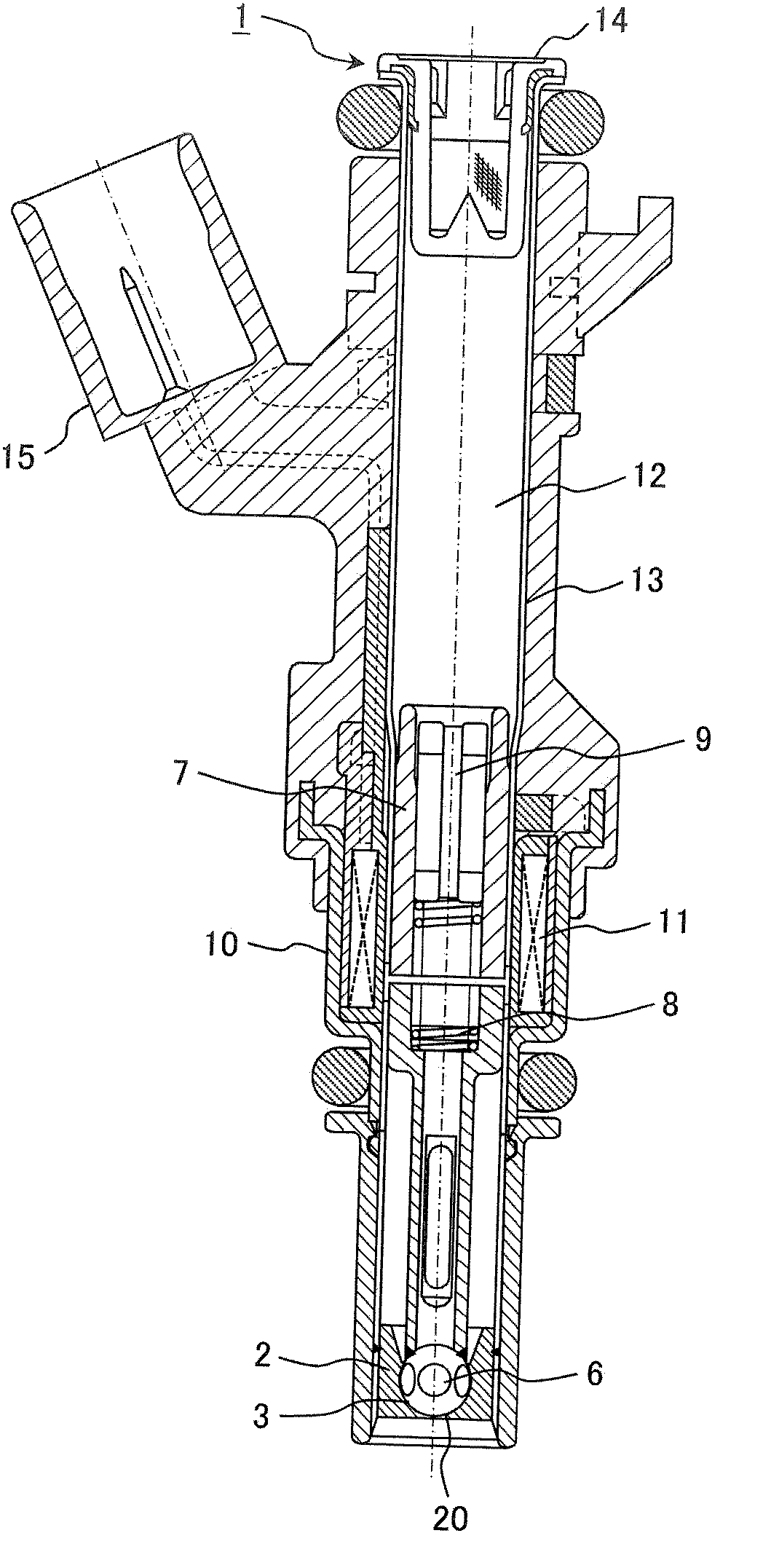
[0036] An embodiment of the present invention will be described below. figure 1 It is a longitudinal sectional view showing the overall configuration of the fuel injection valve 1 of the present invention. exist figure 1 Among them, the fuel injection valve 1 has a structure in which the nozzle body 2 and the valve body 6 are accommodated in a stainless steel thin-walled pipe 13, and the valve body 6 is reciprocated (opened and closed) by an electromagnetic coil 11 arranged outside. . Hereinafter, a detailed structure will be described.

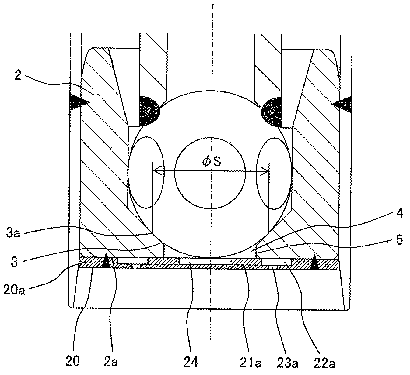
[0037] Equipped with: a magnetic yoke 10 surrounding the electromagnetic coil 11; a magnetic core 7 positioned at the center of the electromagnetic coil 11 and having one end in magnetic contact with the yoke 10; a valve body 6 lifted by a predetermined amount; The valve seat surface 3 of the valve body 6 and the valve seat surface 3 are allowed to pass through the fuel injection chamber 4 through the gap between the valve body 6 and the v...

Embodiment 2

[0083] ・Effect on formation of thickness necessary for processing and flow area

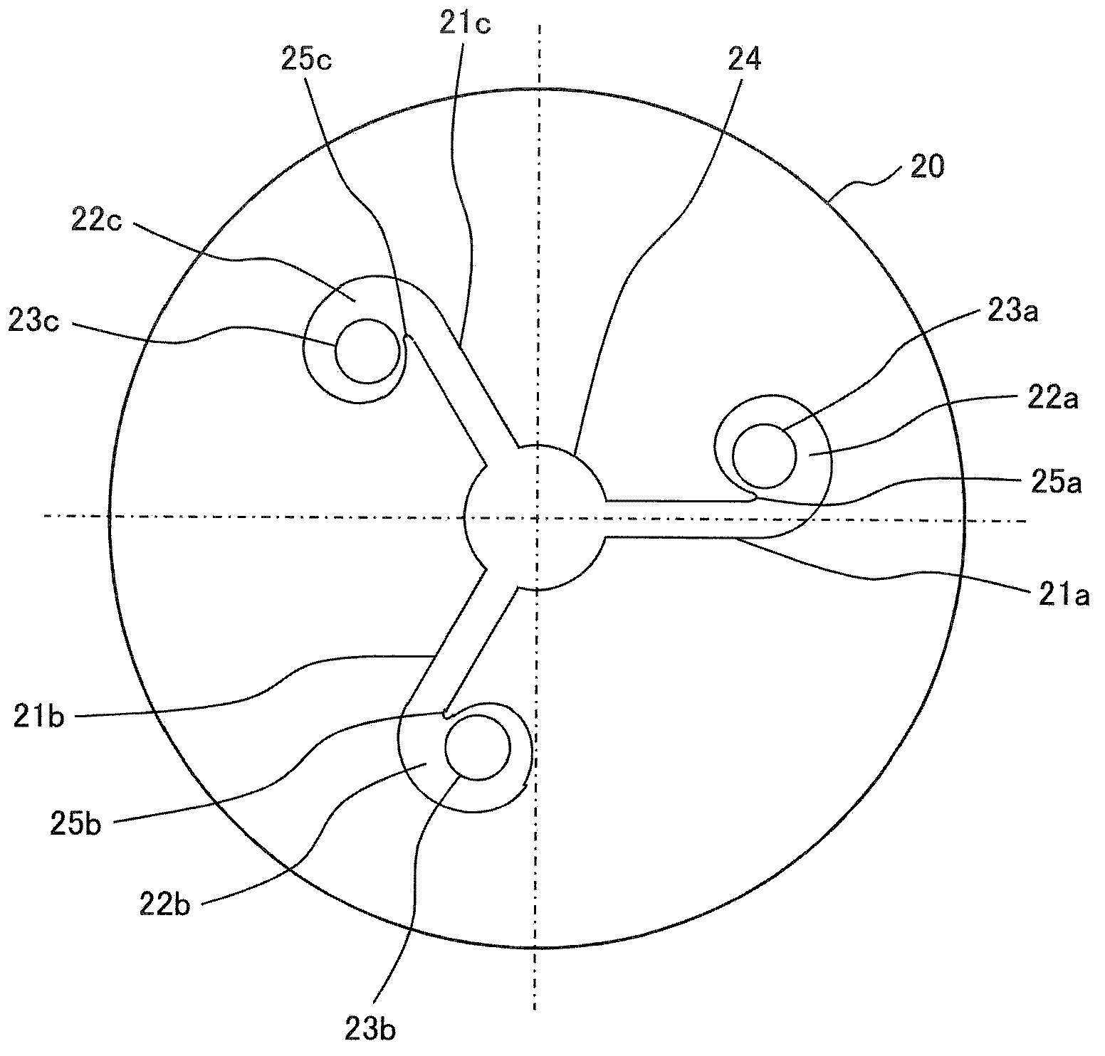
[0084] Below, combine Figure 5 , the thickness 25a necessary for processing to form the connecting portion of the swirl passage 21a and the swirl chamber 22a will be described. Figure 5 It is a figure which shows the relationship of the swirl passage 21a, the swirl chamber 22a, and the fuel injection hole 23a.

[0085] The extension line 22e of the spiral curve drawn by the side wall (wall surface along the height direction) 21ae of the swirl passage 21a and the extension line 22e of the inner peripheral wall of the swirl chamber 22a is rotated (turned) by 180 degrees or more from the starting point S sa of the spiral curve The angular ranges of do not intersect. Thereby, 25a which is a substantial thickness can be formed between the side wall 21ae and the spiral curve drawn by the inner peripheral wall of the swirl chamber 22a.

[0086]Here, the circular portion 25a, which is a thickness ne...


PUM


Abstract

It is an object of the invention to provide a fuel injection valve in which the uniformity of a swirl flow in the circumferential direction is enhanced. The fuel injection valve (1) of the invention includes a swirling chamber (22a-22c) having an inner wall surface comprised of a helical curve and a passage (21a-21c) for swirling for guiding fuel into the swirling chamber (22a-22c). The fuel injection valve (1) is so formed that the center of a circle as the basis of the helical curve and the center of a fuel injection hole (23a-23c) open in the swirling chamber (22a-22c) agree with each other.

Description

technical field [0001] The present invention relates to a fuel injection valve used in an internal combustion engine, and relates to a fuel injection valve capable of improving atomization performance by injecting swirling fuel. Background technique [0002] A fuel injection valve described in Patent Document 1 is known as a conventional technique for promoting atomization of fuel injected from a plurality of fuel injection holes by using a swirling flow. [0003] In this fuel injection valve, between the valve seat member whose downstream end of the valve seat cooperating with the valve body opens to the front end surface and the injector plate joined to the front end surface of the valve seat member, a A horizontal passage connected to the downstream end of the horizontal passage and a swirl chamber in which the downstream end of the horizontal passage opens in a tangential direction, and a fuel injection hole for injecting fuel imparted with a swirl in the swirl chamber i...

Claims


Application Information

Patent Timeline
Patent Type & Authority Applications(China)
IPC IPC(8): F02M61/18
CPCF02M61/162F02M61/1853F02M61/163F02M61/186F02M61/1806F02M61/1846
Inventor 吉村一树冈本良雄石井英二前川典幸斋藤贵博中井敦士
Owner HITACHI ASTEMO LTD
Learn More