Energy storage device for storing energy as spring torsion

A technology for storing energy and energy storage device, which is applied in transmission devices, elastic engines, rotary transmission devices, etc., and can solve the problems of limited load force of one-way bearings, loss of function, and inability to apply large-scale energy storage.

Inactive Publication Date: 2014-02-12
邱垂南
View PDF6 Cites 11 Cited by
  • Summary
  • Abstract
  • Description
  • Claims
  • Application Information

AI Technical Summary

Problems solved by technology

The most notable problem is that the existing patent uses a common vortex spring design, the torsion of the vortex spring is insufficient, and it is difficult to store a large amount of energy in a limited space; in addition, the existing patent only relies on a simple one-way bearing To limit the direction of torque input, and the load force of the one-way bearing is limited, if the input torque is too large, it is easy to damage and lose its function
Therefore, this existing patent can only be applied to small-scale energy storage devices, and cannot be used in large-scale energy storage applications such as power plants.

Method used


Image

  • Energy storage device for storing energy as spring torsion
  • Energy storage device for storing energy as spring torsion
  • Energy storage device for storing energy as spring torsion

Examples


Embodiment Construction

[0041] In order to better understand the technical features of the present invention and the effects it can achieve, preferred embodiments of the present invention will now be described in detail with reference to the accompanying drawings.

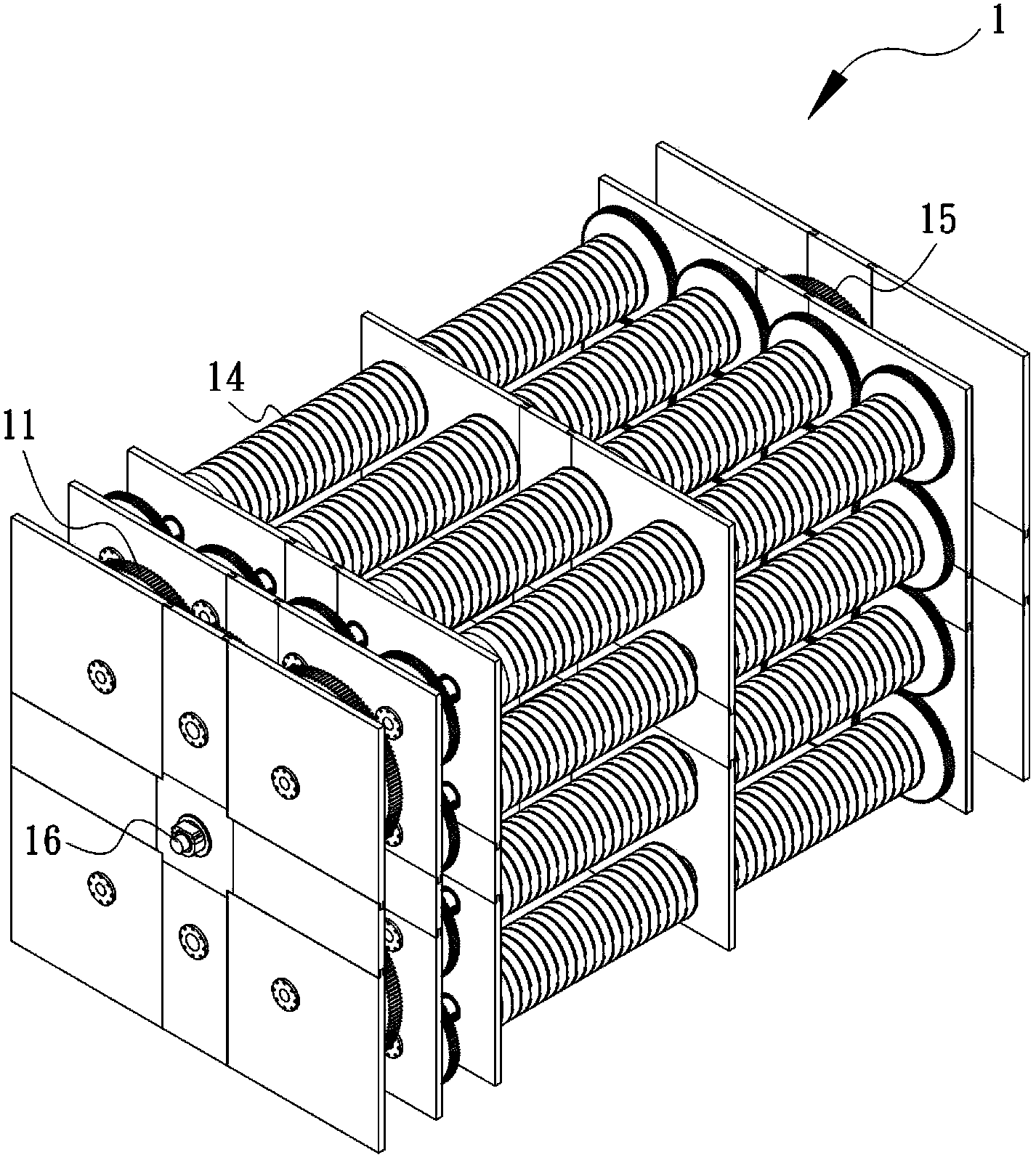
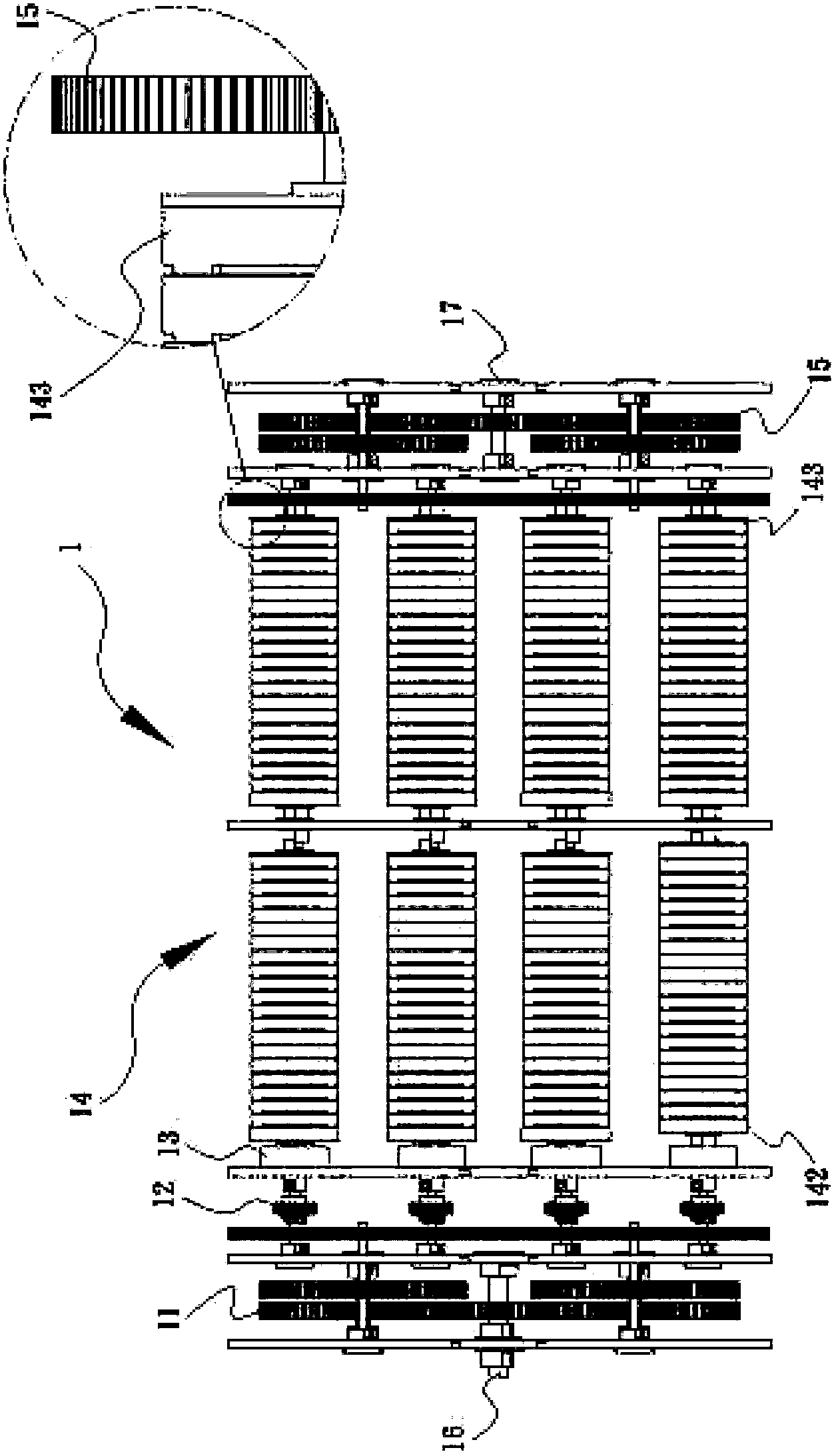
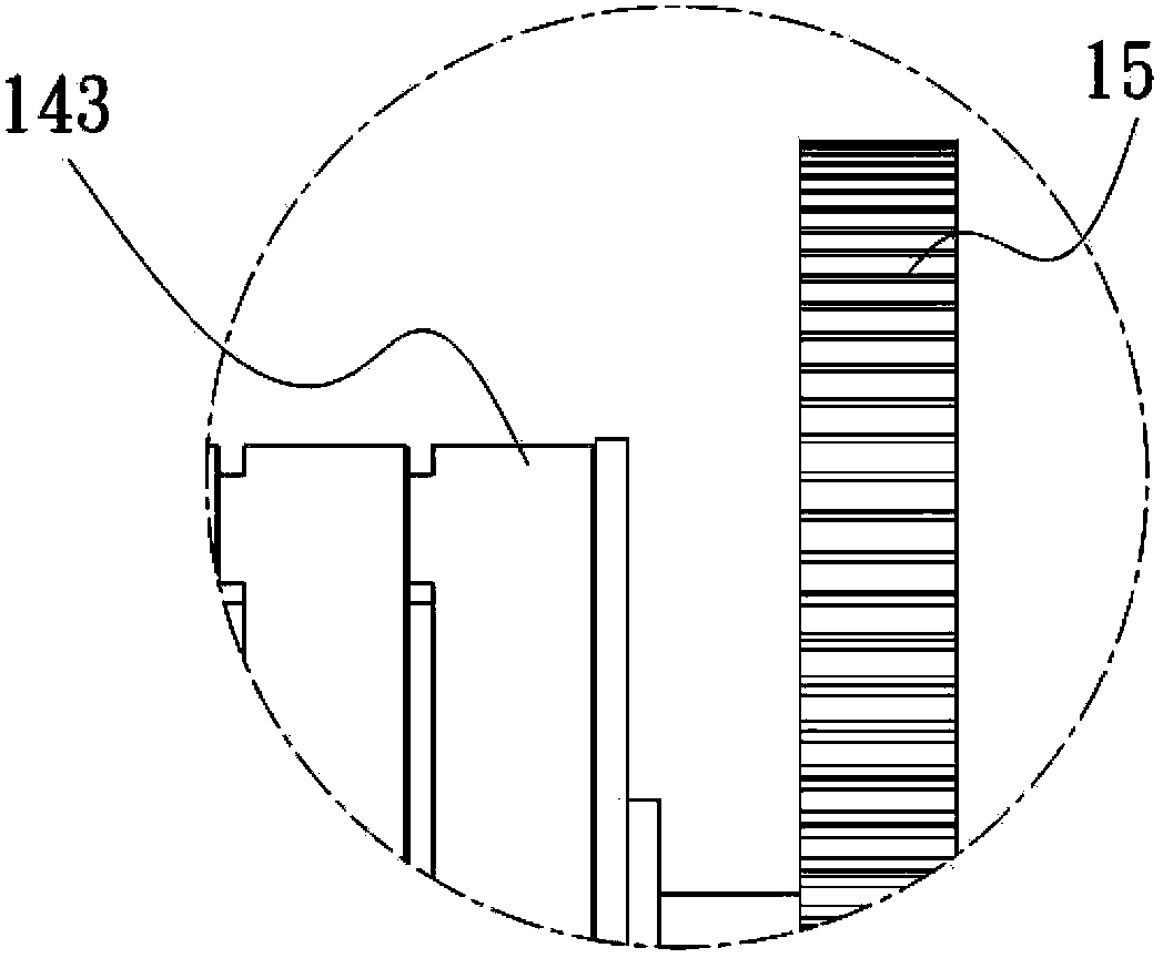
[0042] Such as Figure 1 to Figure 3 As shown, it is an energy storage device 1 that stores energy with spring torque provided by the present invention, which consists of a torque conversion gear 11, a torque limiter 12, a one-way input bearing 13, an energy storage group 14, a speed-up conversion gear 15, etc. Structure and composition. The torque conversion gear 11 is used to connect the energy source, through the torque limiter 12 and the one-way input bearing 13 to limit the magnitude and direction of its energy input, and can be smoothly converted into spring compression energy stored in the energy storage group 14, and then through The speed-up conversion gear 15 releases energy for rear-end use.

[0043]Further, the torque conver...


PUM


Abstract

The invention discloses an energy storage device for storing energy as spring torsion, which is used for storing a motive force generated by an energy generation device in a spring type energy form. The energy storage device for storing the energy as the spring torsion comprises a torsion conversion gear used for connecting an energy source and converting the energy into torsion for outputting; the output end of the torsion conversion gear is connected to a torsion limiter and is used for preventing oversized torsion from being input to subsequent structures to result in damage; the output end of the torsion limiter is connected to a one-way input bearing so as to transmit the torsion to the subsequent structures in a single direction and prevent the output torsion from being output inversely to result in damage to the former structures; the output end of the one-way input bearing is connected to an energy storage group; the energy storage group is formed by coaxially connecting at least two turntables; a torsion spring is wound between two adjacent turntables; the terminal end of the torsion spring is bent in the direction opposite to the winding direction, so that when the turntables rotate, the torsion spring is bent and wound for twice to increase a rotary torsion; the turntable at the torsion output end of the energy storage group is connected to an speed-up conversion gear and is used for speeding up the rotary torsions so as to perform energy outputting; the energy storage group further can be arranged in a serial/parallel mode to increase energy storage and use efficiency.

Description

technical field [0001] The present invention relates to an energy storage device that stores energy by spring torsion, in particular to an energy storage device that accepts various energy sources, converts them into spring compression energy storage, and releases the elastic force to obtain energy output when needed. Background technique [0002] Due to the limited reserves of petrochemical energy on the earth, there will always be a day when it will be exhausted, and most of the petrochemical energy is in the hands of a few countries, which will greatly affect the economy of other countries. In addition, the pollution of petrochemical energy to the environment is quite serious, so how to develop new energy , has become a subject of great concern around the world. [0003] In fact, the earth has a lot of clean energy, including solar energy, wind power, water power, etc. The sources are inexhaustible, and it depends on how to use them effectively. The problem is that these...

Claims


Application Information

Patent Timeline
Patent Type & Authority Applications(China)
IPC IPC(8): F16H33/06
CPCF03G1/02F03G1/00Y02E10/72F03D9/02F16H33/06F16H2706/00Y02E60/16Y02E70/30F03G1/06F03G7/08
Inventor 邱垂南
Owner 邱垂南
Why Eureka
Try Eureka