
pulse valve

A technology of pulse valve and valve cover, applied in the field of pulse valve, can solve the problems of short service life, valve port sealing, vulnerability, etc., and achieve the effect of improving high temperature service performance and reducing sealing points.

Active Publication Date: 2016-05-18
CHENGDU INTERMENT TECH
View PDF5 Cites 1 Cited by
  • Summary
  • Abstract
  • Description
  • Claims
  • Application Information

AI Technical Summary

Problems solved by technology

[0004] During the actual operation, the inventor found that in some occasions (for example, in order to avoid dew condensation on the filter element when filtering and removing high-temperature gas), it is necessary to use high-temperature gas for back-blowing. Some parts are easily damaged and the seal of the moving diaphragm to the valve port is significantly reduced after a long time of use
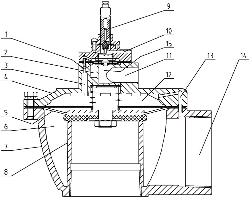
After careful analysis, it was found that: first, when high-temperature gas is used for backflushing, the high-temperature gas will enter the return chamber through the pilot hole, resulting in high temperature of the parts of the end cover, which will cause vulnerability problems; second , the moving diaphragm includes a diaphragm body which is edge-mounted on the valve body, a diaphragm lower pressing plate which doubles as a valve port seal, and a diaphragm upper pressing plate. The diaphragm body is located between the diaphragm lower pressing plate and the diaphragm upper pressing plate and passes The connection mechanism is integrated with the diaphragm lower pressure plate and the diaphragm upper pressure plate, and the diaphragm lower pressure plate is made of rubber, but it is precisely because the diaphragm lower pressure plate is made of rubber material, its service life at high temperature is short, resulting in the valve Mouth sealing problem

Method used


Image

  • pulse valve
  • pulse valve
  • pulse valve

Examples


Embodiment Construction

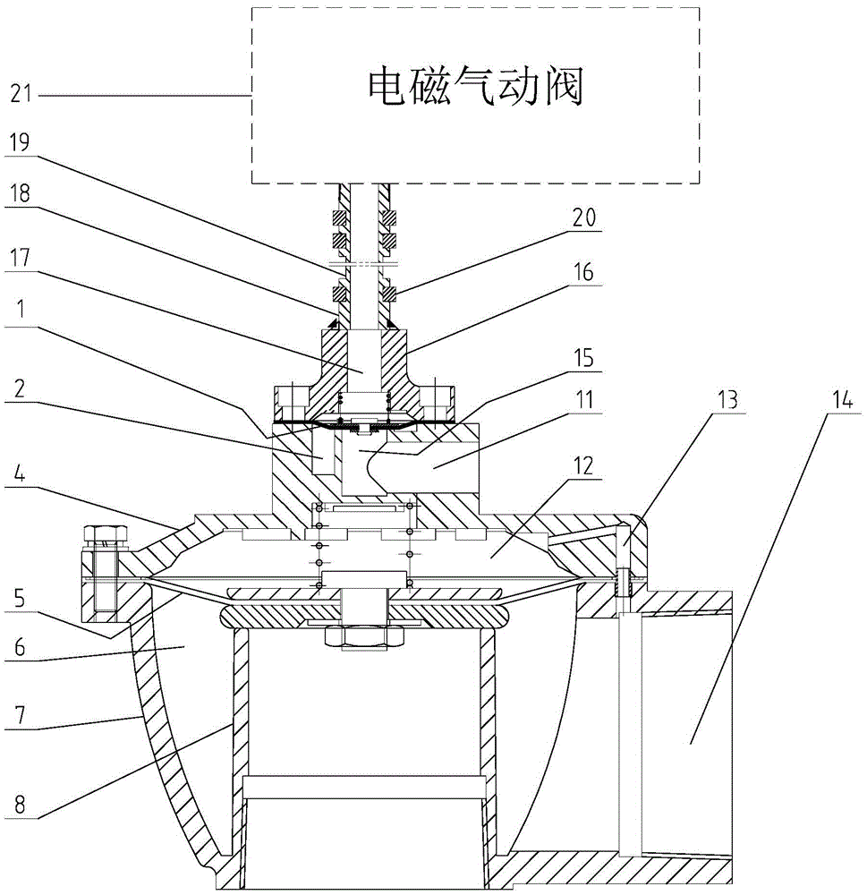
[0012] Such as figure 2 As shown, the pulse valve includes a valve body composed of a valve body 7 and a valve cover 4. A moving diaphragm 5 that can move forward and backward is installed between the valve body 7 and the valve cover 4. There is a valve inside the valve body 7 that can be moved forward. The valve port 8 closed by the moving diaphragm 5 on the top is held by the spring between the moving diaphragm 5 and the valve cover 4 and forms a front air chamber 6 with the valve body 7. The moving diaphragm 5 and the A rear air chamber 12 is formed between the valve covers 4, and the front air chamber 6 and the rear air chamber 12 are communicated through an air guide hole 13 provided in the valve body. Diaphragm 1, the valve cover 4 is located below the upper moving diaphragm 1 and is provided with an air intake chamber 2 and an exhaust chamber 15 that can be blocked by the upper moving diaphragm 1 in the forward position, and the air intake chamber 2 It communicates wi...


PUM


Abstract

The invention discloses a pulse valve which can improve the use performance in high-temperature gas. The pulse valve comprises a valve consisting of a valve body and a valve deck, wherein a moving diaphragm which can move forward and backward is mounted between the valve body and the valve deck; a valve port which can be closed by the moving diaphragm in forward movement position is formed in the valve body; an upper moving diaphragm which can move forward and backward is arranged at the top of the valve deck, and a gland whose gas path is independent from the valve is mounted at the top of the valve deck; the upper moving diaphragm is mounted between the gland and the valve deck and maintained by a spring located between the upper moving diaphragm and the gland, and a return chamber which is adaptive to the upper moving diaphragm is formed in the bottom of the gland; when the upper moving diaphragm moves backwards toward the return chamber, a gas inlet chamber and a gas exhaust chamber are communicated; and a gas vent communicated with the return chamber is formed in the gland and connected with an electromagnetic pneumatic valve, so that control gas controlling the upper moving diaphragm to move forward and backward is input into the gas vent or discharged from the gas vent through the electromagnetic pneumatic valve.

Description

technical field [0001] The invention relates to a pulse valve, in particular to a dust cleaning pulse valve for a high-temperature filter dust collector. Background technique [0002] Industrially used filter dust collectors (such as bag filter, sintered porous membrane filter dust collector) are generally equipped with a back-blowing dust removal device. When the amount of dust attached to the filter element reaches a certain level during filtration, it is necessary to start the back-blowing dust removal The device performs pulse back blowing on the filter element to remove the dust on the filter element, so as to achieve the purpose of reusing the filter element. The pulse valve is a key component of the blowback dust cleaning device, and it is a terminal device that controls the start and stop of the blowback gas. [0003] figure 1 It is the dust cleaning pulse valve for filter and dust collector currently used by the applicant, which includes a valve body composed of a...

Claims


Application Information

Patent Timeline
Patent Type & Authority Patents(China)
IPC IPC(8): F16K7/17B01D46/42
CPCB01D46/4272F16K7/17F16K27/08F16K31/12F16K49/00
Inventor 高麟汪涛方波袁林张宇
Owner CHENGDU INTERMENT TECH
Learn More