Tube

A marking and fluid flow technology, applied in the direction of hoses, pipes, piping systems, etc., can solve problems such as delay in connecting pipes, pipe identification, and inability to fall off marks, so as to reduce costs, save labor and time.

Inactive Publication Date: 2014-02-12
DISCO CORP
View PDF9 Cites 0 Cited by
  • Summary
  • Abstract
  • Description
  • Claims
  • Application Information

AI Technical Summary

Problems solved by technology

[0012] However, as in the prior art, in the method of attaching the cylindrical marks printed with the direction mark indicating the direction of fluid flow and the identification mark indicating the type of tube to both ends of the tube, the f

Method used


Image

  • Tube
  • Tube
  • Tube

Examples


Embodiment Construction

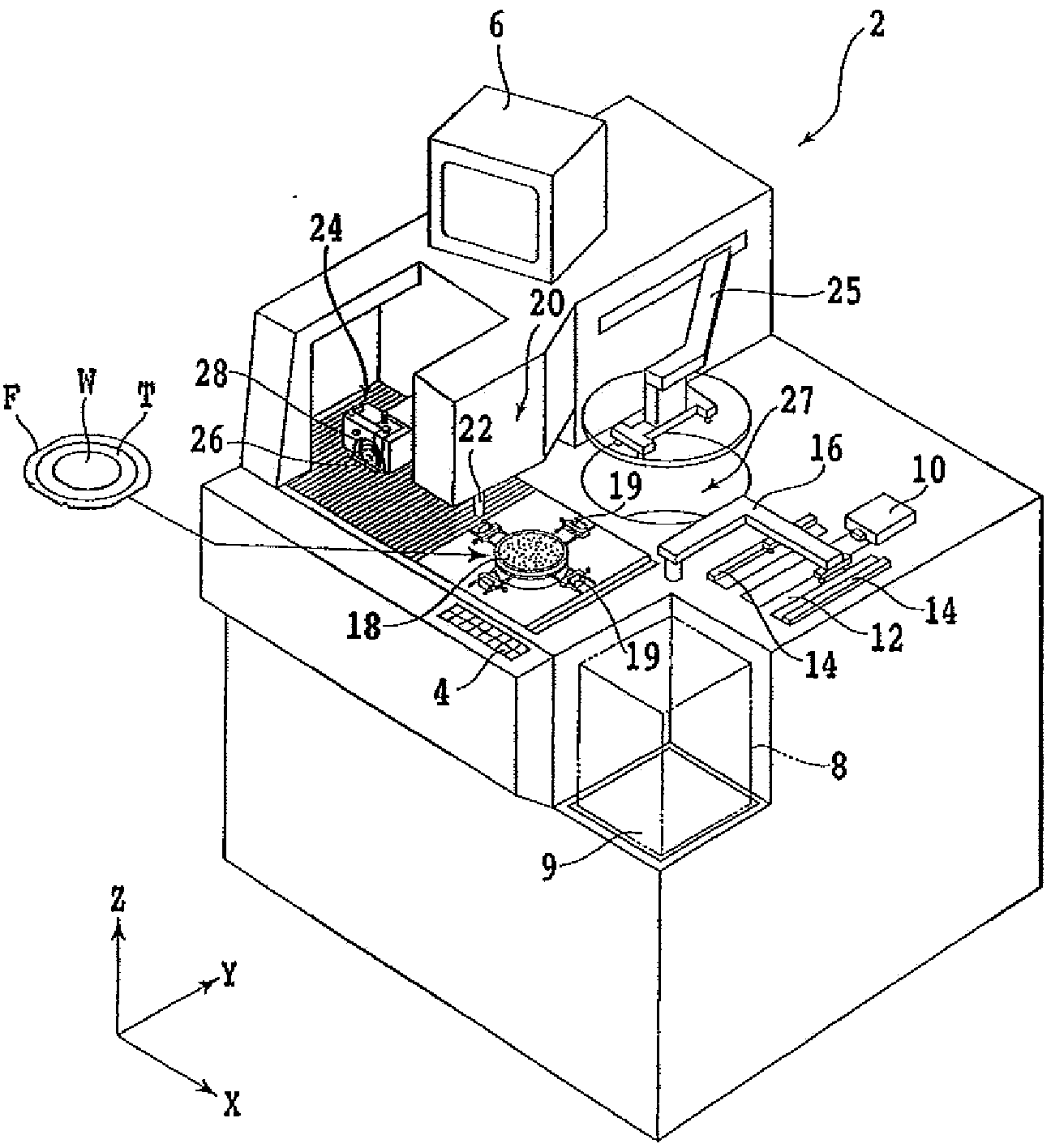
[0034] Hereinafter, embodiments of the present invention will be described in detail with reference to the drawings. figure 1 It is an external perspective view showing a cutting device 2 using the pipe of the present invention for piping. On the front side of the cutting device 2 is provided an operating member 4 for an operator to input instructions to the device such as machining conditions. A display unit 6 such as a CRT is installed on the upper part of the device, and the display unit 6 displays a guidance screen for an operator and an image captured by an imaging unit described later.

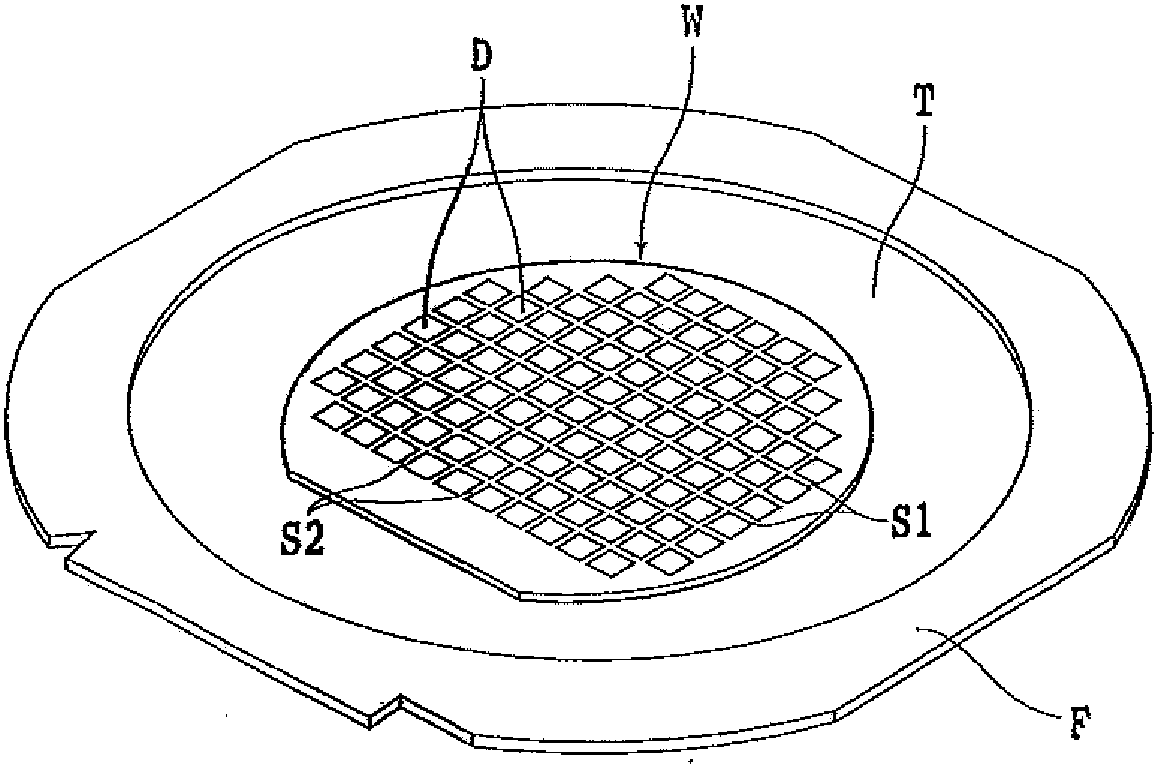
[0035] like figure 2 As shown, on the surface of a light-emitting device wafer W (hereinafter, simply referred to as "wafer W") as a dicing object, first street (segmentation plan line) S1 and second street S2 are formed orthogonally. A plurality of devices D such as LEDs divided by the first spacer S1 and the second spacer S2 are formed thereon.

[0036] The wafer W is attached to a...


PUM


Abstract

The invention provides a tube, capable of smoothing the tube connection in a device. A tube for fluid flowing comprises a direction mark which is printed on the tube for expressing the flowing direction of the fluid, and an identifying mark which is printed on the tube for identifying the tube. The direction mark and the identifying mark are adjacently printed in the extending direction of the tube. The direction mark is formed by the combination of over two straight lines or curved lines. The direction mark and the identifying mark share the same color.

Description

technical field [0001] The present invention relates to tubes for fluid flow. Background technique [0002] Devices using various fluids such as water and air in production machines and manufacturing devices are increasing. For example, the following are known: in the manufacturing process of semiconductor devices, a grinding device called a grinder that grinds a semiconductor wafer to make it thinner or a device that divides a thinned semiconductor wafer into chip shapes is known. A cutting device called a dicing machine is full of pipes that transmit air, machining fluid, suction force, etc. to the required places of the device (for example, refer to Patent Documents 1 and 2). [0003] More specifically, the cutting device has at least: a chuck table for attracting and holding the semiconductor wafer; an air bearing type spindle unit including a cutting tool for cutting the semiconductor wafer held on the chuck table; and a cleaning Apparatus for cleaning cut semiconduct...

Claims


Application Information

Patent Timeline
IPC IPC(8): F16L11/12F16L11/06
CPCF16L11/06F16L11/12F17D3/01H01L21/02
Inventor 砂川武司保本浩
Owner DISCO CORP
Why Eureka
Try Eureka