
Cooking bench air curtain

A stove fan and air curtain technology, which is applied in the field of stove air curtain, can solve the problem of not being able to limit the diffusion of oil fume, and achieve the effect of avoiding too many pipes and reasonable structure

Inactive Publication Date: 2014-02-12
徐李华
View PDF7 Cites 5 Cited by
  • Summary
  • Abstract
  • Description
  • Claims
  • Application Information

AI Technical Summary

Problems solved by technology

[0002] When the existing oil fume cooktop is used, the oil fume permeates the whole kitchen, and the range hood only plays the role of exhausting the oil fume, but cannot limit the diffusion of the oil fume in the kitchen

Method used


Image

  • Cooking bench air curtain

Examples


Embodiment Construction

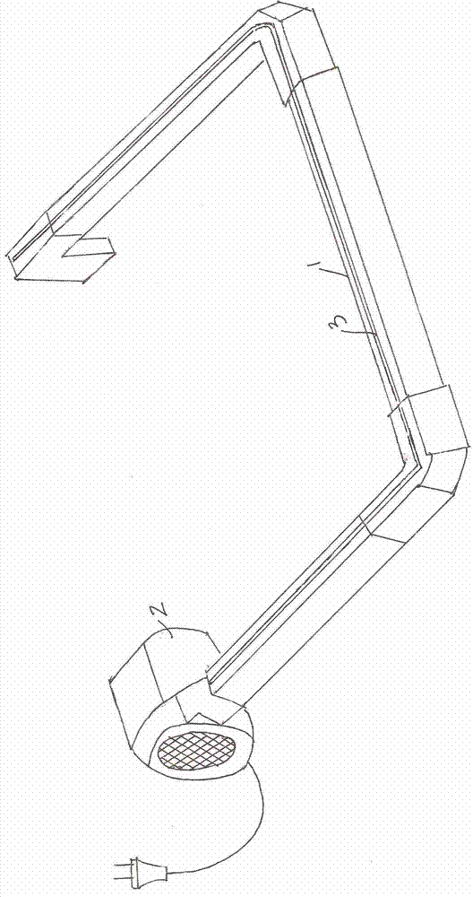
[0011] An air curtain for a cooktop, comprising a U-shaped air duct 1, one end opening of the U-shaped air duct is directly connected to an air outlet of a fan 2, and a long strip outlet forming a U-shaped air curtain is arranged on the upper surface of the U-shaped air duct. Tuyere 3.

[0012] The air outlet of the fan is inserted into the end opening of the U-shaped air pipe, or the end opening of the U-shaped air pipe is inserted into the air outlet of the fan.

[0013] Of course, the air duct can also be in the form of a closed loop, and the fan can be one or more.

[0014] When in use, the air duct is placed on the periphery of the stove, so that the oil fume can be limited to the stove.


PUM


Abstract

The invention discloses a cooking bench air curtain, which comprises a U-shaped opening-type or closed-type annular air pipe, wherein the air pipe is provided with an opening which is directly connected with an air outlet of a fan, and the upper surface of the air pipe is provided with an elongated air outlet forming the air curtain. The cooking bench air curtain is reasonable in structure, the oil smoke can be limited in the area of the cooking bench, and the dispersion of the oil smoke can be limited; the opening of the air pipe is directly connected with the air outlet of the fan, so that the problem of the inconvenience in installation caused by excessive pipelines can be effectively avoided.

Description

technical field [0001] The invention relates to a stove air curtain. Background technique: [0002] When the existing oil fume cooktop is in use, the oil fume permeates the whole kitchen, and the range hood only plays the role of exhausting the oil fume, but cannot limit the diffusion of the oil fume in the kitchen. Contents of the invention [0003] The object of the present invention is to provide a cooker air curtain with a reasonable structure, which can confine the cooking fume in the cooker area and limit the diffusion of the cooking fume. [0004] Technical solution of the present invention is: [0005] An air curtain for a stove, which is characterized in that it includes a U-shaped open or closed annular air duct, the air duct is provided with an opening directly connected to the air outlet of the fan, and a long strip-shaped outlet forming an air curtain is arranged on the upper surface of the air duct. tuyere. [0006] The stove air curtain includes a U-shape...

Claims


Application Information

Patent Timeline
Patent Type & Authority Applications(China)
IPC IPC(8): F24C15/20F24F9/00
CPCF24C15/2028
Inventor 徐李华
Owner 徐李华
Learn More