Efficient heat exchange tube fin for filler coupling coil evaporative condenser

A technology of evaporative condenser and heat exchange fins, which is applied in evaporator/condenser, direct contact heat exchanger, water shower cooler, etc., can solve the problems of reduced heat exchange efficiency, achieve reduced usage, The effect of increasing the evaporation heat transfer surface area and improving the heat transfer effect

Inactive Publication Date: 2014-02-12
GUANGZHOU WIDE IND
View PDF6 Cites 8 Cited by
  • Summary
  • Abstract
  • Description
  • Claims
  • Application Information

AI Technical Summary

Problems solved by technology

In a traditional evaporative condenser, the length and spacing of the heat exchange tubes are the same, and there is no downward slope along the flow direction of the liquid in the tube; due to the temperature and gas-liquid state changes of the liquid in the heat exchange tube from the inlet to the outlet The change in the heat transfer per unit coil area caused by the coil area in different process positions has different requirements for factors such as the flow rate of cooling air, the length of heat exchange tubes, the heat dissipation of cooling water, and the slope of heat exchange tubes. The traditional form of coils cannot meet the above requirements, resulting in a decrease in heat exchange efficiency

Method used


Image

  • Efficient heat exchange tube fin for filler coupling coil evaporative condenser
  • Efficient heat exchange tube fin for filler coupling coil evaporative condenser
  • Efficient heat exchange tube fin for filler coupling coil evaporative condenser

Examples


Embodiment 1

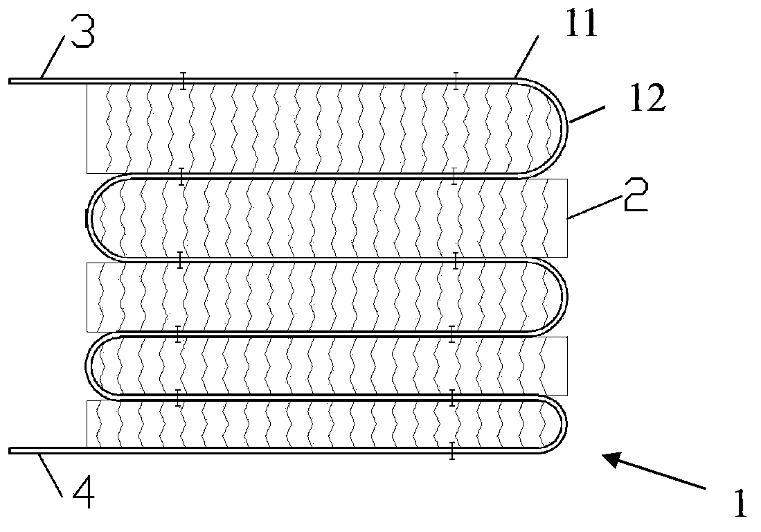
[0037] Image 6 shows another preferred heat exchange fin of the present invention, including coil 1 and packing 2 . The difference from the first embodiment above is that in the heat exchange tube sheet, the length of the straight pipe section of the heat exchange tube 11 gradually increases from the upper layer to the lower layer. To flow down to the heat exchange tube 11 located in the lower floor. The heat exchange fins provided in this embodiment are more suitable for an evaporative condenser using two sets of heat exchangers. Compared with Embodiment 1, in this embodiment, a fan with a larger size and horsepower can be installed by changing the length of the straight pipe section of the heat exchange tube 11 without changing the overall size of the condenser. see again Image 6 , the fans in the solid line are the heat exchange fins provided by this embodiment, and the fans in the dotted lines are the heat exchange fins with heat exchange tubes of equal length and str...


PUM


Abstract

A high-efficient heat exchange tube piece for a filler coupling coil evaporative condenser comprises a coil (1) formed of heat exchange tubes coiled into an S shape. The coil (1) is provided with at least one layer of filler (2) for guiding spraying cooling water to flow from an upper layer heat exchange tube to a lower layer heat exchange tube. The filler (2) is arranged between adjacent heat exchange tubes (11), and connects the heat exchange tubes (11) to form a continuous water flow surface. The heat exchange tube is capable of lowering the temperature of cooling water in a cooling coil, and improving water distribution coverage of cooling water sprayed from the cooling coil and the heat exchange efficiency.

Description

technical field [0001] The invention relates to the field of heat exchange equipment, in particular to a high-efficiency heat exchange tube sheet for a coil evaporative condenser. Background technique [0002] At this stage, evaporative condensers on the market usually use coiled heat exchange tubes to form a heat exchanger. The outer surface of the heat exchanger is cooled by spraying water, and the circulating spraying water is used to evaporate the air and take away the heat. Since there is no medium between the upper and lower tubes of the coil to guide the cooling water flow, when the cooling water falls from top to bottom, under the traction of the vertical wind direction, the cooling water flutters disorderly and easily produces flying water, and the water distribution on the coil is uneven. It is easy to store dry spots, reduces heat exchange capacity and has the risk of fouling, and also has the disadvantages of low heat exchange efficiency, more heat exchanger con...

Claims


Application Information

Patent Timeline
Patent Type & Authority Applications(China)
IPC IPC(8): F28D5/02F28F1/00F28F25/08
CPCF28D5/02F25B39/04F28D3/00F25B2339/041F25B2500/01F28D1/0477F28D2021/007F28F1/22F28F25/087
Inventor 李志明张勇谭栋何卫国
Owner GUANGZHOU WIDE IND
Why Eureka
Try Eureka