Filler coupling coil evaporative condenser

An evaporative condenser and coil technology, applied in evaporator/condenser, water shower cooler, direct contact heat exchanger, etc., can solve the problem of unreasonable utilization of heat exchange area, no mechanical cleaning operation space, increase The use of metal materials and other issues can reduce the risk of scaling, reduce backward drift or flying water, and reduce the cost of use

Active Publication Date: 2014-02-12
GUANGZHOU WIDE IND
View PDF4 Cites 10 Cited by
  • Summary
  • Abstract
  • Description
  • Claims
  • Application Information

AI Technical Summary

Problems solved by technology

The water distribution and ventilation conditions of the coil elbow are poor, and the heat exchange area of ​​this part is not properly utilized
In order to achieve the evaporation capacity and ensure the heat exchange r

Method used


Image

  • Filler coupling coil evaporative condenser
  • Filler coupling coil evaporative condenser
  • Filler coupling coil evaporative condenser

Examples


Embodiment Construction

[0041] The present invention will be further described in detail below in conjunction with the embodiments and the accompanying drawings, but the embodiments of the present invention are not limited thereto.

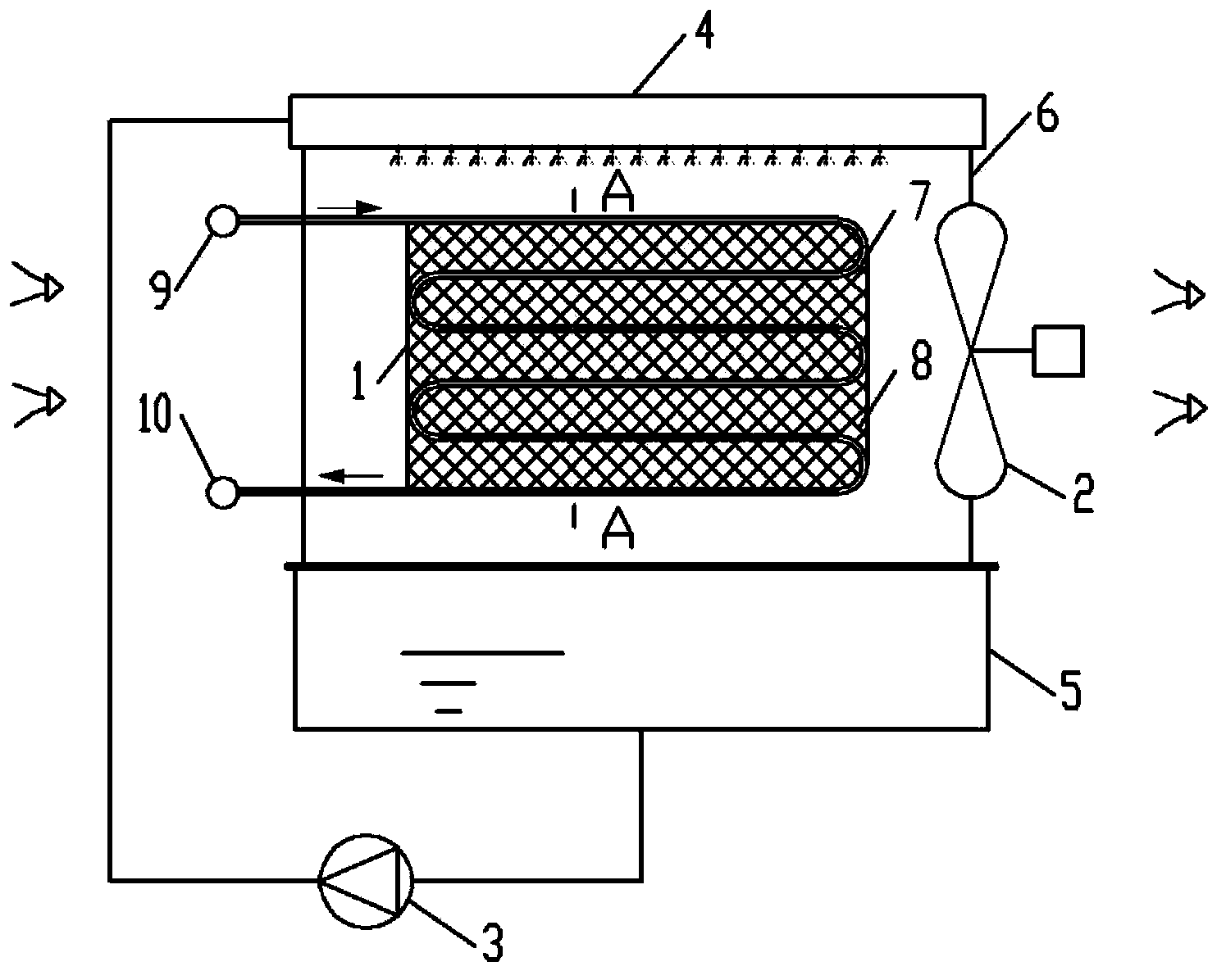
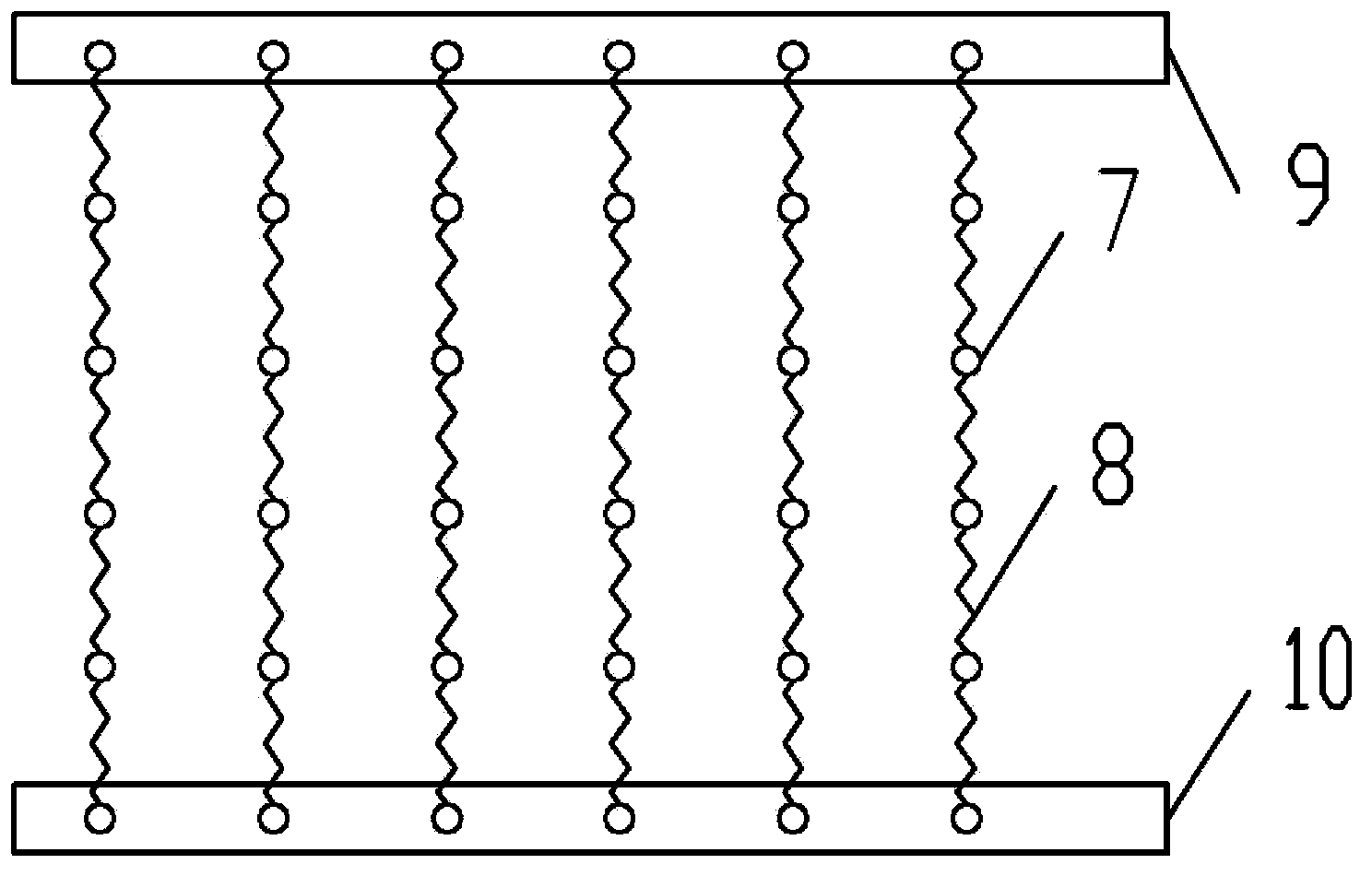
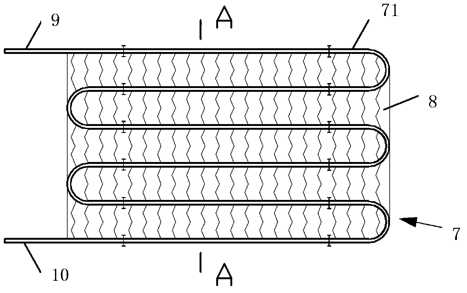
[0042] figure 1 , figure 2 The structure of the evaporative condenser of the present invention is shown, and the evaporative condenser includes a coil heat exchanger 1, a fan 2, a water pump 3, a water distributor 4, a sump 5 and a frame 6; the heat exchanger 1 consists of The heat exchange tube fins formed by a plurality of serpentine coils are connected by an inlet header 9 and an outlet header 10 . Each heat exchange fin includes a longitudinal serpentine (S-shaped) coil 7 and packing 8. The packing is arranged between the plane spaces formed by the serpentine coil. The packing and the coil form a tightly fitting structure, that is, the two are coupled. connected to form a segment structure. The coil is arranged vertically, that is, the cooling air blown by the fa...


PUM


Abstract

The invention provides a filler coupling coil evaporative condenser. The filler coupling coil evaporative condenser comprises a coil heat exchanger, a fan, a water pump and a water distributor. The coil heat exchanger is formed by connecting a plurality of heat exchange tube fins through inlet headers and outlet headers, each heat exchange tube fin comprises a coil and filler, and the coil is provided with at least one piece of filler for guiding spraying cooling water to flow from an upper-layer heat exchange tube to a lower-layer heat exchange pipe. The filler coupling coil evaporative condenser can reduce the temperature of the cooling water of the cooling coils, improve the coverage rate of water distribution of the cooling water of the cooling coils, improve heat exchange efficiency, prevent water flying, and reduce ventilation resistance; has the advantages of being large in heat transfer area and easy to clean; is wide in application range and good in market prospect.

Description

technical field [0001] The invention relates to the field of heat exchange equipment, in particular to an evaporative condenser with a coil tube as a heat exchanger. Background technique [0002] At present, the coils used in evaporative condensers on the market are horizontal coils. The outer surface of the coil is cooled by spraying water, and the circulating spraying water is used to evaporate the air and take away the heat. Since there is no medium between the upper and lower tubes of the coil to guide the cooling water flow, when the cooling water falls from top to bottom, under the traction of the vertical wind direction, the cooling water flutters disorderly and easily produces flying water, and the water distribution on the coil is uneven. It is easy to store dry spots, reduce heat transfer capacity and have a risk of fouling. The cooling air direction is perpendicular to the coil (that is, the cooling air passes through the plane space formed by each heat exchange ...

Claims


Application Information

Patent Timeline
IPC IPC(8): F28D5/02F28F1/00F28F25/08
CPCF28F25/02F28D1/0477F28D5/02F28F25/08F28F1/00F28F1/20F25B39/04F25B2339/041
Inventor 李志明
Owner GUANGZHOU WIDE IND
Why Eureka
Try Eureka