
A water chiller with packing coupling coil evaporative condenser

A technology for evaporative condensers and water chillers, which is applied in the direction of evaporators/condensers, refrigerators, refrigeration components, etc., can solve the problems of no mechanical cleaning operation space, difficult cleaning, and increased coil length, etc. The effect of reducing the risk of fouling, improving heat exchange efficiency, and low cost of use

Active Publication Date: 2016-12-21
GUANGZHOU WIDE IND
View PDF6 Cites 0 Cited by
  • Summary
  • Abstract
  • Description
  • Claims
  • Application Information

AI Technical Summary

Problems solved by technology

Since the cooling air direction is perpendicular to the coil (that is, the cooling air passes through the plane space formed by each heat exchange fin and is perpendicular to the straight pipe section of the heat exchange tube), the coil will have a windward side and a leeward side. The lack of air convection heat transfer reduces the heat transfer efficiency of the coil
On the other hand, due to the small effective heat exchange area of ​​the horizontal coil, the length of the coil needs to be increased. At the same time, due to the misalignment of the tubes of the traditional horizontal coil, there is no room for mechanical cleaning, and it is also difficult to clean. Shortcomings
Therefore, the lack of transverse coils greatly limits the application of evaporative condensers in chillers

Method used


Image

  • A water chiller with packing coupling coil evaporative condenser
  • A water chiller with packing coupling coil evaporative condenser
  • A water chiller with packing coupling coil evaporative condenser

Examples


Embodiment 1

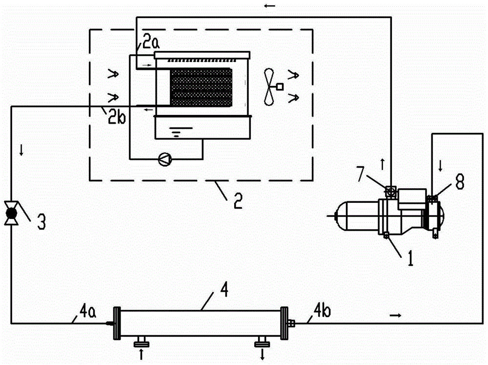
[0044] figure 1 A schematic diagram showing the principle of the refrigerating cycle mode of the water chiller of the present invention, by figure 1 It can be seen that the water chiller includes a compressor 1, an evaporative condenser 2, a throttling device 3 and an evaporator 4; the exhaust port 7 of the compressor is connected with the gas pipe 2a of the evaporative condenser, and the evaporative condenser The liquid pipe 2b is connected to the liquid pipe 4a of the evaporator through a throttling device, and the gas pipe 4b of the evaporator is connected to the suction port 8 of the compressor. The evaporative condenser 2 adopts longitudinally arranged coils coupled with fillers, which will not be described in detail here.

[0045]The working principle of the present invention: when the refrigerant is compressed by the compressor 1 and becomes a high-temperature and high-pressure gas, it enters the evaporative condenser 2 through the refrigeration system pipeline, and af...

Embodiment 2

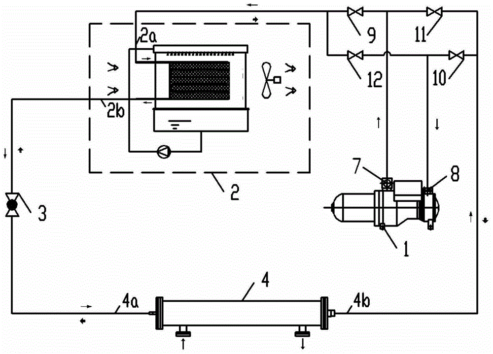
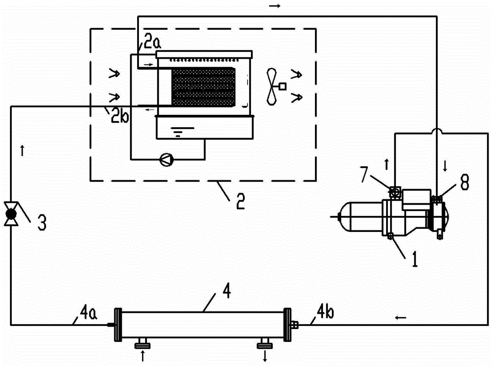
[0047] figure 2 It shows a schematic diagram of the principle of the water chiller of the present invention. Compared with Embodiment 1, the difference is that the water chiller is provided with a first refrigeration valve 9, a second refrigeration valve 10, a first heat pump valve 11 and a second refrigeration valve. Two heat pump valves 12; the first refrigeration valve 9 is arranged on the connecting pipeline between the exhaust port 7 of the compressor and the gas pipe 2a of the evaporative condenser, and the second refrigeration valve 10 is arranged on the air inlet 8 of the compressor and the evaporator On the connecting pipeline of the gas pipe 4b of the evaporator, the first heat pump valve 11 is arranged on the connecting pipeline between the exhaust port 7 of the compressor and the gas pipe 4b of the evaporator, and the second heat pump valve 12 is arranged on the suction of the compressor. On the connecting pipeline between port 8 and gas pipe 2a of the evaporative...

Embodiment 3

[0050] Figure 4 It shows a schematic diagram of the principle of the water chiller of the present invention using a two-position three-way reversing valve. Compared with Embodiment 1, the difference is that the exhaust port 7 of the compressor 1 is provided with a first two-position three-way Reversing valve 13, the suction port 8 of the compressor is provided with a second two-position three-way reversing valve 14; the two outlets of the first two-position three-way reversing valve 13 are respectively connected to the gas pipe 2a and the gas pipe 2a of the evaporative condenser The gas pipe 4b of the evaporator is connected, and the two inlets of the second two-position three-way reversing valve 14 are respectively connected with the gas pipe 2a of the evaporative condenser and the gas pipe 4b of the evaporator. Also, the evaporative condenser 2 employs packing-coupled longitudinally arranged coils.


PUM


Abstract

The invention provides a water chiller with packing coupling coil evaporative condenser, which includes a compressor, an evaporative condenser, a throttling device and an evaporator; the evaporative condenser includes a coil heat exchanger, a fan, a cloth water tank and sump; the coil heat exchanger is composed of a plurality of heat exchange tubes connected by inlet headers and outlet headers; the heat exchange tubes include coils and fillers, and the coils are equipped with at least A piece of filler used to guide the spray cooling water to flow from the upper heat exchange tube to the lower heat exchange tube. The coil is arranged vertically, that is, the cooling air blown by the fan flows along the approximate length direction of the straight pipe section of the coil . The invention can reduce the cooling water temperature of the cooling coil, increase the water distribution coverage of the cooling water of the cooling coil, has the advantages of high heat transfer efficiency, wide application range and good market prospect.

Description

technical field [0001] The invention relates to the field of air conditioning equipment, in particular to a chiller of a coil evaporative condenser. Background technique [0002] The use of evaporative condensers to release heat into the outdoor air and apply them to chillers is an important way to achieve high-efficiency and stable refrigeration. Compared with water-cooled condensers and air-cooled condensers, its heat transfer efficiency is high, and it has a significant prospects for energy saving and emission reduction. At this stage, the evaporative condenser coils used in chillers on the market are horizontal coils. The outer surface of the coil is cooled by spraying water, and the circulating spraying water is used to evaporate the air and take away the heat. Since the cooling air direction is perpendicular to the coil (that is, the cooling air passes through the plane space formed by each heat exchange fin and is perpendicular to the straight pipe section of the hea...

Claims


Application Information

Patent Timeline
Patent Type & Authority Patents(China)
IPC IPC(8): F25B13/00F25B39/02F25B41/04F25B41/20
CPCF25B13/00F25B39/04F28D5/02F28F25/087F28D1/0477F25B2313/02732F25B2313/02741F25B2313/02791F25B2339/041
Inventor 李志明
Owner GUANGZHOU WIDE IND
Learn More