A flow instrument and its liquid circuit system and method

A liquid system and flow instrument technology, applied in the field of particle analysis, can solve problems such as low measurement efficiency, measurement interruption, and inconvenient use, and achieve the effects of shortening detection time, accurate counting, and avoiding interruption

Active Publication Date: 2018-07-17
SHENZHEN MINDRAY BIO MEDICAL ELECTRONICS CO LTD +1
View PDF6 Cites 0 Cited by
  • Summary
  • Abstract
  • Description
  • Claims
  • Application Information

AI Technical Summary

Problems solved by technology

This kind of scheme requires the method of back-calculating the sample volume with the help of known concentration standard particles, which requires the user to accurately prepare the concentration of standard particles, which has high requirements for users, is inconvenient to use, and increases the cost of use for users.
The conventional absolute volume measurement method needs to use a quantitative pump to quickly push the sample. Since the volume of each quantitative measurement is limited, when the sample push cannot meet the needs, the quantitative pump needs to suck the sample again and push the sample again, which wastes time and leads to sample loss. There is a problem of measurement discontinuity in the measurement, and multiple quantitative cycle measurements have the disadvantages of high sample waste rate and low measurement efficiency

Method used


Image

  • A flow instrument and its liquid circuit system and method
  • A flow instrument and its liquid circuit system and method

Examples


Embodiment 1

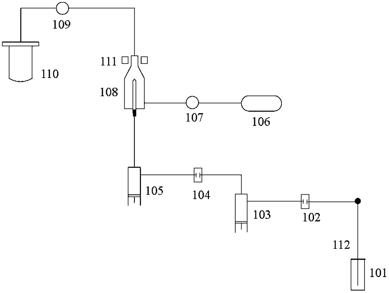
[0036] Please refer to figure 1 , the waste liquid absorbing device comprises a waste liquid pool 110 and a first control valve 109 for containing the waste liquid flowing out from the flow chamber, and the first control valve 109 is arranged on the pipeline between the waste liquid pool 110 and the outlet of the flow chamber 108, And controllable to switch between the open and closed states; the sheath fluid supply device includes a reservoir 106 for containing the sheath fluid and a second control valve 107, and the second control valve 107 is arranged between the reservoir 106 and the flow chamber 108 on the pipeline between the inlets, and can be switched between open and closed states in a controllable manner. The quantification device includes a first quantification device 103 and a second quantification device 105 , the sample supply device is a sampling needle 112 , and the sampling needle 112 can be inserted into the sample tube 101 to suck a sample. The first quanti...

Embodiment 2

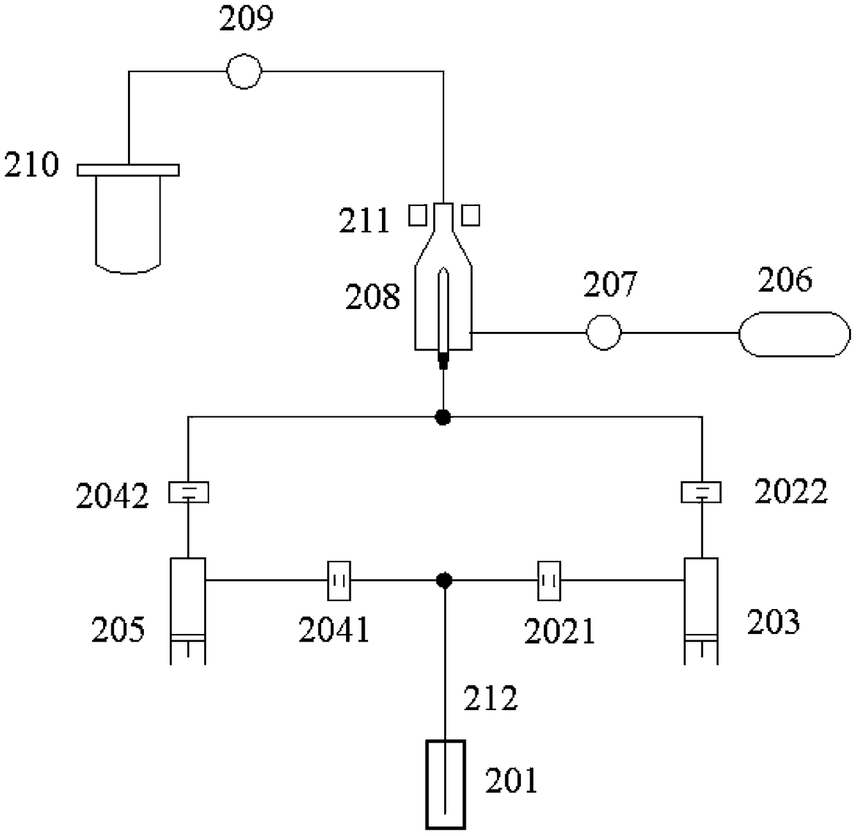
[0049] Please refer to figure 2 , the waste liquid absorbing device comprises a waste liquid pool 210 and a first control valve 209 for containing the waste liquid flowing out from the flow chamber, and the first control valve 209 is arranged on the pipeline between the waste liquid pool 210 and the outlet of the flow chamber 208, And controllable to switch between the open and closed states; the sheath liquid supply device includes a liquid storage tank 206 for containing the sheath liquid and a second control valve 207, and the second control valve 207 is arranged between the liquid storage tank 206 and the flow chamber 208 on the pipeline between the inlets, and can be controlled to switch between the open and closed states. The quantification device includes a first quantification device 203 and a second quantification device 205 , the sample supply device is a sampling needle 212 , and the sampling needle 212 can be inserted into the sample tube 201 to suck a sample. Th...


PUM


Abstract

The invention discloses a flow type instrument, a liquid path system thereof and a method. The liquid path system comprises a flow chamber, a sample providing device, a sheath fluid supplying device, a waste liquid absorption device and N quantifying devices, wherein pipelines of all quantifying devices are respectively communicated with the flow chamber and the sample providing device, and N is greater than or equal to 2. Each quantifying device absorbs quantified sample liquid from the sample providing device according to a set time sequence, and samples are conveyed to the flow chamber according to a predetermined pushed sample amount by at least one quantifying device at each period of time, so that the samples can be continuously fed into the flow chamber; the pushed sample amount is predetermined, so that the volume of a tested sample can be accurately quantified, the accurate counting is realized, the interruption of a testing process is avoided, the continuous measurement for the samples is realized, and the sample detection time is shortened.

Description

technical field [0001] The invention relates to the field of particle analysis, in particular to a flow instrument and its liquid path system. Background technique [0002] Flow cytometers are usually used for the analysis and statistics of tiny particles. In the medical field, flow cytometers are also called flow cytometers, which are used to classify and count cells. Therefore, it is usually required to obtain the total number of collected cells. However, in some cases, the user needs to obtain the concentration information of the collected cells in the sample, so the flow cytometer is required to perform absolute counts on some samples during use to obtain the concentration information of the collected cells, and for most of the remaining What the sample needs is non-absolute counting (that is, common measurement), so as to meet the demand for the collected total number of collected cells. [0003] In order to make the flow cytometer not only meet the requirements of the...

Claims


Application Information

Patent Timeline
Patent Type & Authority Patents(China)
IPC IPC(8): G01N15/10
Inventor 闫宝华廖垂鑫闫华文
Owner SHENZHEN MINDRAY BIO MEDICAL ELECTRONICS CO LTD
Why Eureka
Try Eureka