
Safety fill tank system pressurized by separate nitrogen tank

A technology of safe injection and nitrogen, which is applied in a field of application, can solve problems such as unsatisfactory devices or methods, and achieve the effect of increasing the injection volume

Inactive Publication Date: 2016-05-18
KOREA ATOMIC ENERGY RES INST
View PDF8 Cites 0 Cited by
  • Summary
  • Abstract
  • Description
  • Claims
  • Application Information

AI Technical Summary

Problems solved by technology

However, no device or method has been proposed to meet the above requirements

Method used


Image

  • Safety fill tank system pressurized by separate nitrogen tank
  • Safety fill tank system pressurized by separate nitrogen tank
  • Safety fill tank system pressurized by separate nitrogen tank

Examples


Embodiment Construction

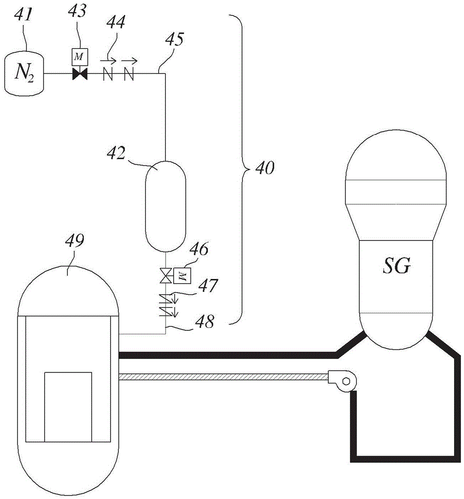
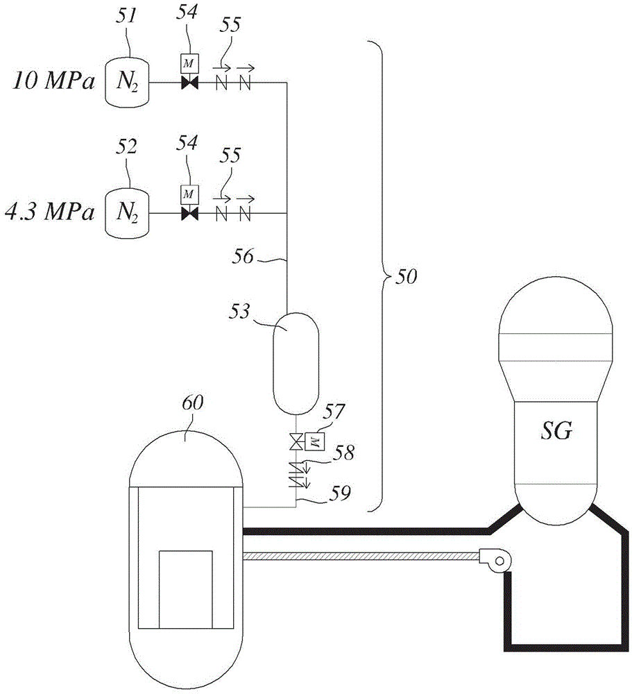
[0038] Hereinafter, a nitrogen tank separation type safety injection tank system pressurized by a separate nitrogen tank according to the present invention will be described in detail with reference to the accompanying drawings.

[0039] Here, it should be noted that the following description only relates to the embodiments for realizing the present invention, but the present invention is not limited to the following embodiments described herein.

[0040] In other words, as will be described later, the present invention relates to a nitrogen tank separate type safety injection tank system pressurized by a separate nitrogen tank in which the nitrogen tank is separated from the emergency core cooling The water tanks are separated from each other, and the two tanks are connected by pipes, thereby substantially preventing phase contact between the emergency core cooling water and the nitrogen gas at the free surface in the conventional safety injection tank when in an operational s...


PUM


Abstract

Disclosed herein is a safety injection tank system, in which the emergency core cooling water tank and the nitrogen tank are isolated from each other. A system pressurized through a separate nitrogen tank prevents nitrogen dissolution and is available for both large and small tube break accidents.

Description

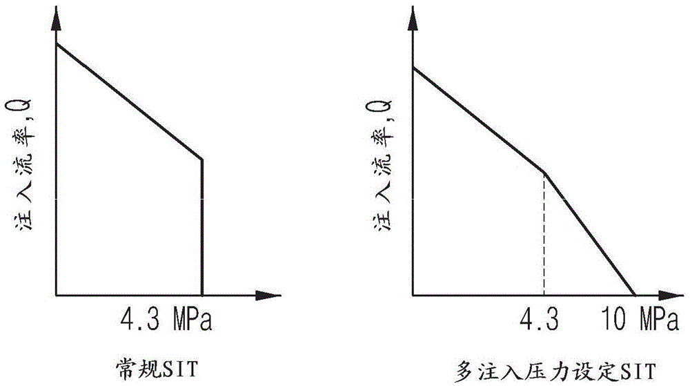
technical field [0001] The present invention generally relates to a high-pressure safety injection tank system for an emergency core cooling system of a nuclear reactor, and more particularly, to a safety injection tank system in which an emergency core cooling water tank is connected with a The nitrogen tanks are separated from each other, thereby solving the problem in the conventional one-piece safety injection tank system in which the nitrogen gas and the emergency core cooling water are received in the same tank, so that the nitrogen gas dissolves in the emergency core cooling water and It is then injected into the nuclear reactor system while it is on operational standby, thus disrupting the formation of the natural circulation loop for heat transfer or heat exchange. [0002] Furthermore, the present invention relates to a safety injection tank system comprising a plurality of nitrogen tanks for high pressure and low pressure purposes, thus enabling it to be applied to ...

Claims


Application Information

Patent Timeline
Patent Type & Authority Patents(China)
IPC IPC(8): G21C15/18
CPCG21C15/18Y02E30/30G21C15/02
Inventor 权泰纯金起焕宋哲和梁俊彦白原弼
Owner KOREA ATOMIC ENERGY RES INST
Learn More