Thermo-magnetic protection device and electric protection device of thermo-magnetic protection device

A protection device, thermo-magnetic technology, applied in the direction of protection switch operation/release mechanism, etc., can solve the problems of inability to repeat adjustment, plastic deformation, affecting production efficiency, etc. Effect

Inactive Publication Date: 2014-02-12
XIAMEN HONGFA ELECTRICAL SAFETY & CONTROLS CO LTD
View PDF0 Cites 2 Cited by
  • Summary
  • Abstract
  • Description
  • Claims
  • Application Information

AI Technical Summary

Problems solved by technology

[0003] This thermomagnetic protection device and the electrical protection equipment including the device have the following disadvantages: 1. The thermal protection mechanism and the electromagnetic mechanism interact with each other. The tripping current of the short-circuit protection is greatly increased; this makes the circuit breaker fail to trip smoothly and cause serious accidents if a short circuit occurs when the circuit is overloaded; 2. The thermal magnetic protection mechanism uses the elasticity of the terminal board to adjust and fix the gap e ' and d', since the wiring board is made of copper, it is prone to stress fatigue and plastic deformation, so it is often shaped during adjustment and cannot be adjusted repeatedly, which greatly affects production efficiency; 3. The wiring board is both a mechanical part and a flow guide For the sake of structural strength, the wiring board needs to be designed to be large and complex, and the amount of copper used is high and the cost is high.

Method used


Image

  • Thermo-magnetic protection device and electric protection device of thermo-magnetic protection device
  • Thermo-magnetic protection device and electric protection device of thermo-magnetic protection device
  • Thermo-magnetic protection device and electric protection device of thermo-magnetic protection device

Examples


Embodiment Construction

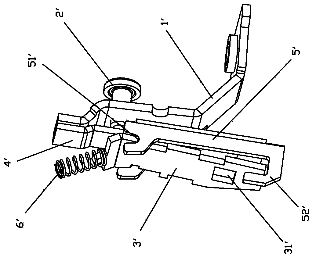
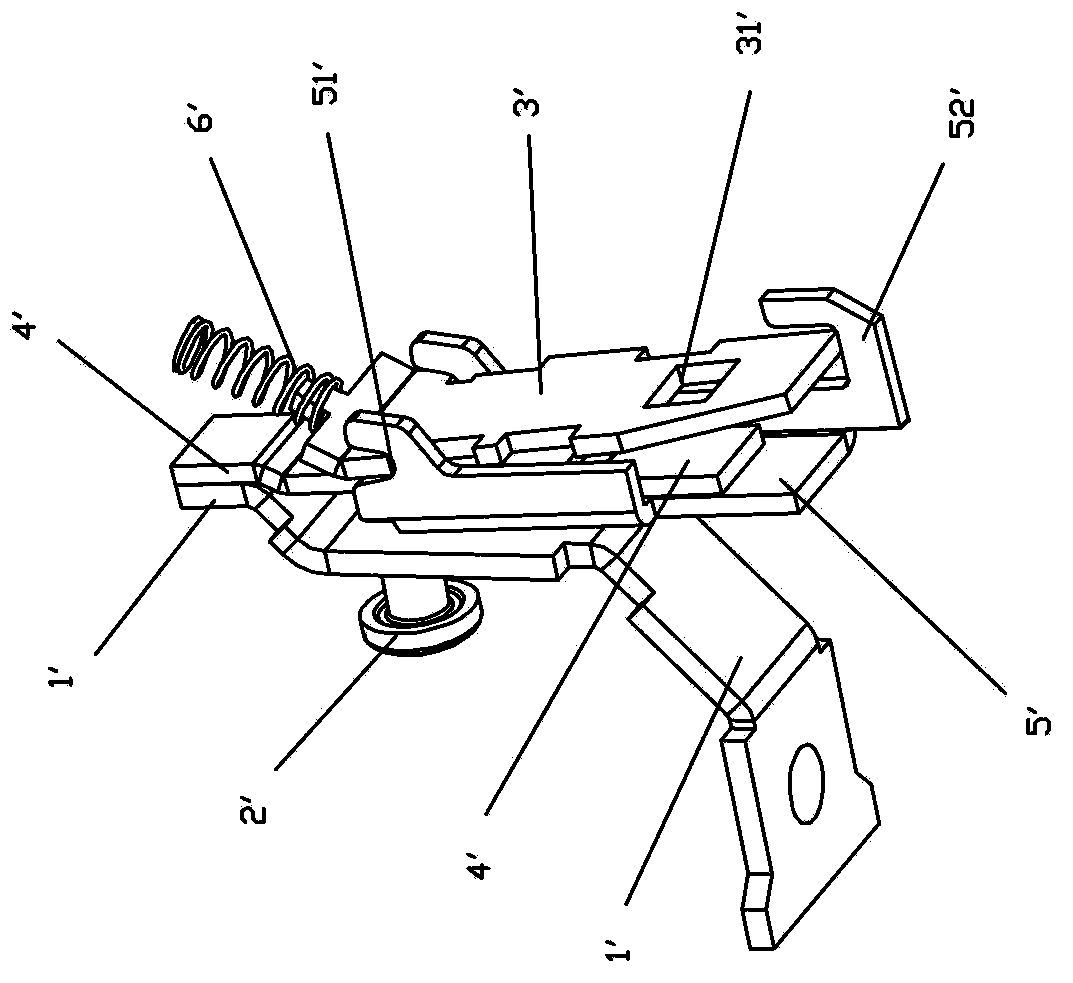
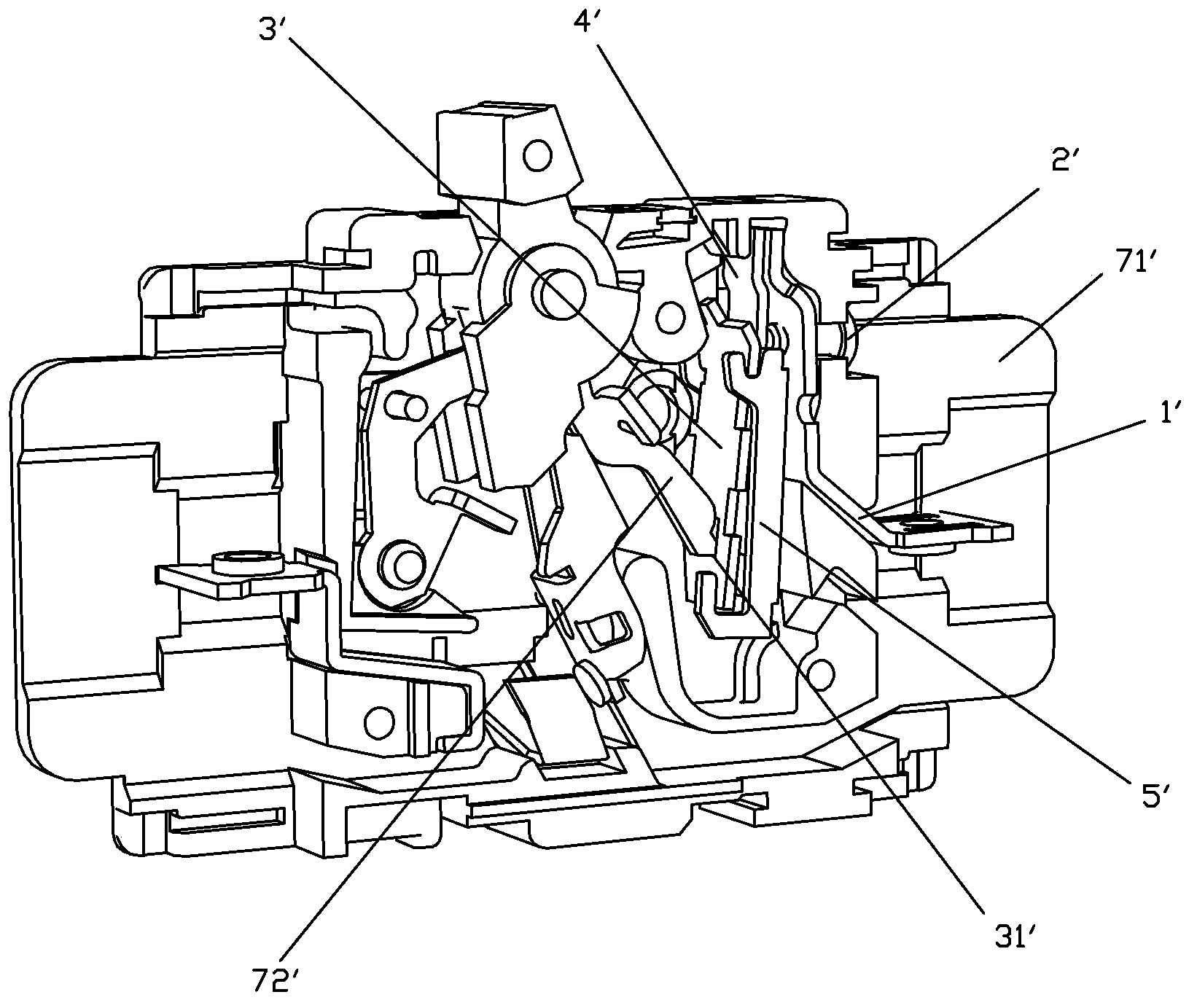
[0027] Examples, see Figure 5 to Figure 7 As shown, a thermal-magnetic protection device of the present invention is used on a circuit breaker. The thermal-magnetic protection device includes a terminal board 1, an adjusting screw 2, an armature 3, a bimetallic element 4, a yoke 5 and a reaction spring 6 The wiring board 1 is fixed on the preset support body; the armature 3 is suspended in the groove 51 of the yoke 5, and the upper part of the armature 3 is fixed on the preset support body through the reaction force spring 6; it also includes A twisted wire 7; one end 52 of the yoke is clamped on a preset support body, and the other end 53 is elastically bent so as to have a preset angle a with the first end 52, the The adjustment screw 2 is screwed on one end 52 of the yoke, and the end of the adjustment screw 2 is against the other end 53 of the yoke with elastic force, so as to adjust the preset angle a through the adjustment screw. size; the bimetallic element 4 is place...


PUM


Abstract

The invention discloses a thermo-magnetic protection device and an electric protection device of the thermo-magnetic protection device. The thermo-magnetic protection device comprises a wiring board, an adjusting screw, an armature, a bimetallic element, a magnet yoke, a counter-force spring and a strand line. The wiring board is fixed on a supporting body, the armature is hung on the magnet yoke and fixed through the counter-force spring, one end portion of the magnet yoke is clamped on the preset supporting body, the other end portion of the magnet yoke is elastically bent to enable a preset included angle a to be formed between the other end portion of the magnet yoke and the one end portion of the magnet yoke, the adjusting screw is connected to the one end portion of the magnet yoke in a screwed mode, and the tail end of the adjusting screw abuts against the other end portion, provided with the elastic force, of the magnet yoke, and therefore the preset included angle a is adjusted through the adjusting screw. The bimetallic element is arranged in the other end portion of the magnet yoke, the bimetallic element and the other end portion of the magnet yoke are fixed, and the bimetallic element is connected with the wiring board through the strand line. The thermo-magnetic protection device and the electric protection device of the thermo-magnetic protection device have the advantages of being simple in design, high in reliability, less in copper using quantity and low in manufacturing cost.

Description

technical field [0001] The invention relates to electrical protection equipment, in particular to a thermomagnetic protection device for a circuit breaker and the electrical protection equipment including the device. Background technique [0002] At present, thermal magnetic low-voltage circuit breakers are widely used in power distribution systems or equipment lines to provide protection for power distribution lines or equipment. Generally, thermal magnetic circuit breakers realize overload, overheating and short circuit protection through functional components such as thermal protection mechanism and electromagnetic mechanism. At present, there are two mainstream structures in thermal magnetic circuit breakers in the market: one is that the thermal protection mechanism and the electromagnetic mechanism are separated independently, and the other is that the thermal protection mechanism and the electromagnetic mechanism are combined to form a whole with thermal protection. ...

Claims


Application Information

Patent Timeline
Patent Type & Authority Applications(China)
IPC IPC(8): H01H71/40
Inventor 王慧德徐明
Owner XIAMEN HONGFA ELECTRICAL SAFETY & CONTROLS CO LTD
Why Eureka
Try Eureka