Primary equipment intelligent interface device in substation

A technology of primary equipment and intelligent interface, applied in the direction of circuit devices, electrical components, etc., can solve problems such as burnout, contact jamming, and inherent delay increase, and achieve the effects of overcoming many faults, improving reliability, and simplifying the circuit

Active Publication Date: 2014-02-12
SHENZHEN POWER SUPPLY BUREAU
View PDF4 Cites 12 Cited by
  • Summary
  • Abstract
  • Description
  • Claims
  • Application Information

AI Technical Summary

Problems solved by technology

[0003] 1. Electromagnetic relays are affected by operating conditions and years, which can easily cause contact jamming, insulation reduction, burning, etc., and the reliability cannot be guaranteed continuously;
[0004] 2. The inherent time delay of the electromagnetic relay may increase with the increase of the operation period and the weakening of the mechanical stress, especially for the uncontrollable influence on the reliability of protection opening and closing;
[0006] 4. It does not have the function of monitoring and counting primary equipment state quantities such as switch opening / closing current, opening / closing time, energy storage suppression time, etc., which is not conducive to timely discovery of potential hidden dangers of switches;
[0007] 5. It is impossible to monitor and send an alarm signal when the control circuit of the knife switch and ground knife is disconnected or the intermediate relay is damaged, especially for the situation that the insulation of the relay is reduced and the malfunction is not detected in advance.
[0008] 6. The number of auxiliary contacts used is large, the circuit and installation and construction are complicated
From years of operating experience, it can be found that various problems in the auxiliary secondary circuit will reduce the reliability and operating life of the entire primary equipment, thus affecting the entire life cycle of equipment assets

Method used


Image

  • Primary equipment intelligent interface device in substation
  • Primary equipment intelligent interface device in substation
  • Primary equipment intelligent interface device in substation

Examples


Embodiment Construction

[0045] The invention provides an intelligent interface device for primary equipment. The intelligent interface device replaces the traditional electromagnetic relay circuit with logic operation, and realizes the state monitoring of the primary equipment of the substation, and has self-checking and communication functions at the same time.

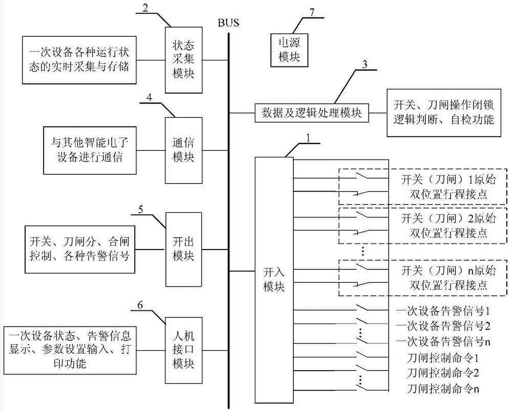
[0046] see figure 2 , is a schematic structural diagram of Embodiment 1 of the smart interface device for primary equipment provided by the present invention. An intelligent interface device for primary equipment provided by the present invention includes:

[0047] Input module 1, state acquisition module 2, data and logic processing module 3, communication module 4, output module 5, man-machine interface module 6, power supply module 7. Except the power supply module 7, other modules are connected through the bus.

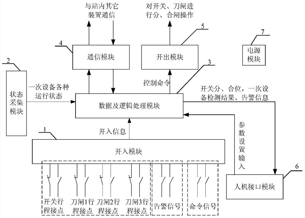
[0048] For details, please refer to image 3 , image 3A schematic structural diagram of Embodiment 2 of the smart inter...


PUM


Abstract

The invention provides a primary equipment intelligent interface device in a substation. The device comprises a driving-in module, a state collecting module, a communication module, a driving-out module, a man-machine interface module, and a data and logic processing module which are connected through a bus. According to the primary equipment intelligent interface device in the substation, logic operation is used for replacing a traditional electromagnetic relay circuit, so that the state of primary equipment of the substation can be detected. The device has a self-detection function and a communication function, can effectively overcome the defects that the number of failures of a traditional relay circuit is large, and the failures in operation can not be detected, can detect the state of a switch and other primary equipment in real time, simplifies a circuit, simplifies installation, improves efficiency of operation on the primary equipment, and improves the reliability of operation of the primary equipment.

Description

technical field [0001] The invention relates to the field of electric power technology, in particular to an intelligent interface device for primary equipment in a substation. Background technique [0002] At present, the connection between the primary equipment and the secondary equipment in the substation, such as the switch, the local operation of the knife switch, the electrical interlocking circuit, etc., mostly uses a circuit composed of electromagnetic relays, and passes through several layers of resetting. This multiple reset circuit composed of electromagnetic relays has the following disadvantages: [0003] 1. Electromagnetic relays are affected by operating conditions and years, which can easily cause contact jamming, insulation reduction, burning, etc., and the reliability cannot be guaranteed continuously; [0004] 2. The inherent time delay of the electromagnetic relay may increase with the increase of the operation period and the weakening of the mechanical s...

Claims


Application Information

Patent Timeline
Patent Type & Authority Applications(China)
IPC IPC(8): H02J13/00
Inventor 马镇威李林发姚森敬章彬李艳张胜宝罗杰邓世聪汪桢子黄福全黄颖祺黄荣辉巩俊强吴宗熙伍国兴汪鹏姜云峰张文张瑞李健伟曾乔迪
Owner SHENZHEN POWER SUPPLY BUREAU
Why Eureka
Try Eureka